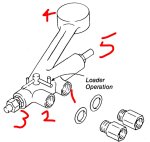
Yes, the lines that carry continuous flow, even when the loader is not being used. Remember, this is an open center system.Many thanks ProTreeBoy. When you say "the main lines", do you mean the line from the hydraulic block to the valve and the line from the valve power beyond port back to the valve ?
And thanks for the link to the sizing chart.
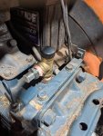
What size are the lines on the tractor side? No point in making the new lines bigger than the existing ones on the tractor.

 .
.