Front loader for a B7200

Paul Allwood

Member
Premium Member

Equipment
Kubota B7200HSTD, RC60-72H MMM
Jul 8, 2025
80
38
18
Baranduda, Victoria, Australia
If you haven't made your SSQA yet, you could consider instead doing the older proprietary Kubota quick attach. I only say this since it seems like all the implements you're going to use you're going to fabricate anyway. The Kubota quick attach is quite a bit lighter than an SSQA setup. I ended up putting one on my B2601 since in New Zealand basically nobody has SSQA, and I would have had to special order it. It was just as easy to order the older quick attach, and it meant I didn't have to modify my bucket.
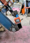
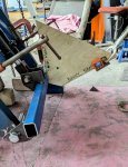
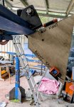
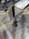
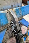
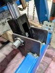
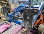
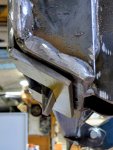
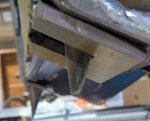
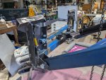
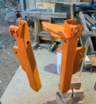
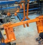
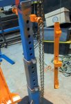
Thanks Paul. You're right, I'll probably make the implements I'm going to use initially, at least for now. I hadn't considered the older style, and chose to make the SSQA style so that it is compatible with other things here in Australia if I do need to buy something, or even borrow an attachment from a friend. I'm also a bit far down the track to change now.
 

Hugo Habicht

Well-known member
Lifetime Member

Equipment
G1900
Jun 24, 2024
682
884
93
Ireland
PS - I used to model things like this in Solidworks which takes out a good bit of the guesswork..... I've now resorted to hand sketches and plywood or cardboard models, which often means more grinding and re-welding later, but it's the best I can do.
Hello Paul,

I use Visio (or LibreDraw) for planning geometries. Not as powerful as Solidworks but faster than making cardboard or plywood templates. You can group parts and rotate them around pivoting points, so easy to check angles and if you hit something I find it very useful.

Also this web site is handy to calculate deflection of steel sections, so you get an idea what is required so that you can keep the weight down: Link steel calculator
 
  • Like
Reactions: 1 user

Paul Allwood

Member
Premium Member

Equipment
Kubota B7200HSTD, RC60-72H MMM
Jul 8, 2025
80
38
18
Baranduda, Victoria, Australia
Hello Paul,

I use Visio (or LibreDraw) for planning geometries. Not as powerful as Solidworks but faster than making cardboard or plywood templates. You can group parts and rotate them around pivoting points, so easy to check angles and if you hit something I find it very useful.

Also this web site is handy to calculate deflection of steel sections, so you get an idea what is required so that you can keep the weight down: Link steel calculator
Thanks Hugo.
 

North Idaho Wolfman

Moderator
Staff member
Lifetime Member

Equipment
L3450DT-GST, Woods FEL, B7100 HSD, FEL, 60" SB, 743 Bobcat with V2203, and more
Jun 9, 2013
33,592
8,831
113
Sandpoint, ID
If this is as far back as you can get the cylinder to go, it's very likely that there is a stop inside the cylinder that needs to be removed.

What bore and stoke is the cylinder?

1755620930736.png
 
  • Like
Reactions: 1 user

Paul Allwood

Member
Premium Member

Equipment
Kubota B7200HSTD, RC60-72H MMM
Jul 8, 2025
80
38
18
Baranduda, Victoria, Australia
If this is as far back as you can get the cylinder to go, it's very likely that there is a stop inside the cylinder that needs to be removed.

What bore and stoke is the cylinder?

View attachment 160976
It's 2.5" bore x 8" stroke. This model of cylinder does use an internal stop, without it it's the same as a 10" stroke cylinder. I can only assume they do it so they have more common parts in manufacturing.

So with the internal stop in place, it still gives a stroke of 8" (LA344 spec is 7.7"). The stop can stay where it is - this is the stroke I want to match the LA344.
 
Last edited:

Paul Allwood

Member
Premium Member

Equipment
Kubota B7200HSTD, RC60-72H MMM
Jul 8, 2025
80
38
18
Baranduda, Victoria, Australia
With the original geometry that was based on plywood and cardboard models, I ended up with a total bucket rotation of 110 degrees with my first set of steel brackets. I was aiming to match the LA344 that I'm roughly copying - this gets a total bucket rotation of about 140 degrees.

Out with the graph paper and pencil, ground off three of the original brackets and made new ones with some small adjustments. The hole in the bracket at the top of the dump cylinder moved up and forwards 13 mm. The holes in the brackets at the bottom of the dump cylinder moved down 18 mm.

The result:
- Total bucket rotation 139 deg
- Max roll back angle at 150 mm 30 deg
- Max dump angle at 1000 mm 72 deg
- Max dump angle at 1800 mm 39 deg

This geometry matches that of the LA344 as close as I can get it. It does put the pivot points closer to being in line at full curl and full dump than I would have expected before getting started on this project, but it appears to work for the LA344. If it turns into a problem, there's always the grinder. I won't know now until I can try it.

Next step - finish welding the bits I tacked in place then onto the SSQA and bucket.
 

Attachments

Last edited:
  • Like
Reactions: 2 users