Reviving a G1900

Hugo Habicht

Member

Equipment
G1900
Jun 24, 2024
84
92
18
Ireland
Some cosmetics

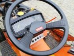
Yes, I know cosmetics should come later but I am using the tractor for cutting the lawn grass and I could not stick the steering wheel centre cover missing, so I splashed out and bought a brand new one for about 25€. And cleaned the manky steering wheel. Looks much better now, I think. :)

IMG_20241101_085958.jpg

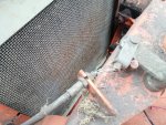
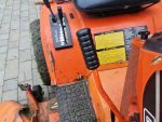
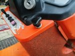
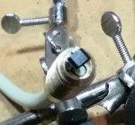
Also the cover under the dash board was held by a coach screw on one side. Really bugged me having to get a screw driver every time I wanted to take the cover off. So I bought 5 of those knob screws M6x20 for 6 quid on ebay (original is M6x15), fitted a DIN 1440 big washer over it and a soft padding cut from a cork/rubber gasket material. Love it !
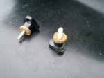
IMG_20241101_170131.jpg

IMG_20241101_170229.jpg
 
Last edited:
  • Like
Reactions: 1 user

Hugo Habicht

Member

Equipment
G1900
Jun 24, 2024
84
92
18
Ireland
Cutting deck

The position of the cutting deck was wrong as explained by some helpful members here on the forum.

The RC48-G20 is the right deck for this tractor but the front linkage is the wrong type. It was from another deck and had been cut and welded already but was still too long.

The adjustment range on the threaded part was at it's end already. I had ordered an M20x1 die for increasing the threaded length but when I wanted to do it I noticed that 1. the thread is rolled, not cut and 2. I could not turn the die holder with the other arm of the u-shaped linkage in the way. Right.

So I simply bent both arms a bit more in a hydraulic press and now I could adjust the deck properly without the anti scalp rollers touching the ground.

Got two suitable pins for the rear wheel and machined 2 14mm pins for the front linkage. Somebody had put an M14 bolt in there. Took ages to take that off every time I wanted to take the deck off. Piece of cake now.

Looking forward to trying it out when its a bit drier :)
 
Last edited:
  • Like
Reactions: 1 user

Hugo Habicht

Member

Equipment
G1900
Jun 24, 2024
84
92
18
Ireland
Throttle linkage

When taking off the dashboard to check the temperature gauge I noticed the bowden cable of the throttle linkage was badly frayed.

IMG_20241104_110034.jpg

IMG_20241104_110040.jpg

I removed the linkage and wanted to reuse the outer part, just give it a new plastic sleeve. But when I took it off I noticed it had chafed thin in one point.

IMG_20241104_113043.jpg

So I replaced the outer and inner part, machined two ferrules and soldered them on.

IMG_20241104_144220.jpg

Cleaned under the dashboard, replaced the grommet, assembled everything and added washers in the u shaped parts to get rid of the play and center the wire.

IMG_20241104_152427.jpg

IMG_20241104_152355.jpg

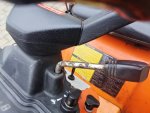
The throttle lever was badly corroded.

IMG_20241104_104054.jpg

I made a new one from stainless steel and polished it a bit. I reused the plastic handle.

IMG_20241104_170809.jpg
 
Last edited:
  • Like
Reactions: 1 user

Hugo Habicht

Member

Equipment
G1900
Jun 24, 2024
84
92
18
Ireland
PTO lever adjustment

Despite having replaced the PTO v-belts by Mitsuboschi belts in the correct size the deck would not start properly when engaging the PTO lever. I noticed that somebody had replaced the PTO brake adjustment bolt by one that was too long and the head hit the frame and prevented full movement of the pulley idler wheel lever. I replaced it with a shorter bolt (orange arrow) and adjusted the gap to the brake lever to 3mm.

IMG_20241104_184452.jpg

The PTO lever adjustment is the spring length inside the hooks to 90mm length when engaged (yellow arrows). The PTO lever works fine now.

And while I was at it I made a handle for the lever that had been missing.

IMG_20241104_103937.jpg

IMG_20241104_103953.jpg

One word about the v-belts. Since there are two in parallel they have to be bought in matched pairs. The Mitsuboshi ones that Kubota is supplying are manufactured to very low tolerances so that matching is not necessary.
 
Last edited:
  • Like
Reactions: 1 user

TheOldHokie

Well-known member
Lifetime Member

Equipment
L3901/LA525, B7200DT/B1630, G2160/RCK60, G2460/RCK60
Apr 6, 2021
8,928
4,667
113
Myersville, MD
windyridgefarm.us
PTO lever adjustment

Despite having replaced the PTO v-belts by Mitsuboschi belts in the correct size the deck would not start properly when engaging the PTO lever. I noticed that somebody had replaced the PTO brake adjustment bolt by one that was too long and the head hit the frame and prevented full movement of the pulley idler wheel lever. I replaced it with a shorter bolt (orange arrow) and adjusted the gap to the brake lever to 3mm.

View attachment 141297

The PTO lever adjustment is the spring length inside the hooks to 90mm length when engaged (yellow arrows). The PTO lever works fine now.

And while I was at it I made a handle for the lever that had been missing.

View attachment 141295

View attachment 141296

One word about the v-belts. Since there are two in parallel they have to be bought in matched pairs. The Mitsuboshi ones that Kubota is supplying are manufactured to very low tolerances so that matching is not necessary.
JFYI - improvements in v-belt manufacturing technolgy pretty much eliminated the need for belt matching years ago. For example Gates V80 manufacturing standard meets or exceeds the RMA matching standard (below) right out of the box.

1000000771.jpg


Dan
 

Attachments

  • Like
Reactions: 1 user

Hugo Habicht

Member

Equipment
G1900
Jun 24, 2024
84
92
18
Ireland
I was not idle the past few weeks, so a short update here.

Combination Box

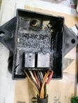
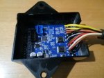
the starter output of the combination box was faulty. I was not willing to pay 250 quid for some simple electronics. I found forum threads where people cut open the box and replaced the relais, certainly a good solution.

A few people mentioned problems with the electrics of this tractor, I guess a majority of those problems are caused by safety switches and this box.

So I wanted some extra test indicators so see what is wrong with the electrics. Hence I knit my own combination box electronics, the board is ready and the software written and tested.

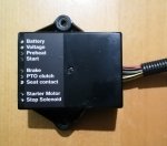
I have included LEDs for all inputs and outputs that will be visible on the outside of the box. So without having to revert to pulling covers and connectors apart I will be able to see what is going wrong.

Also when trying to start and the starter not working the pre glow lamp will show a blink code of the reason the starter is not running (brake, PTO, short, open circuit). An override function will allow me to start the tractor despite errors being present (turn key three times between pre glow and ignition).

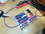
This is my test setup:

IMG_20241215_194050.jpg

And the board itself. Relais replaced by semiconductor switches and an extra input added for external engine stop in case of major faults (temperature and oil pressure) controlled from an instrument cluster controller that I designed as well.

IMG_20241215_194155.jpg

Here you can see the LEDs bent around the side that will be visible on the outside of the box then.

IMG_20241215_194247.jpg

I was looking for a damaged box for the connector because I was hesitant butchering my partly working box before the replacement is fully working. But I had no success, so I will have to use my own box now.

I also worked on the instruments and have ordered some material for more repairs, I will show the results soon.

Kind regards,
Hugo
 
Last edited:
  • Like
  • Wow
Reactions: 3 users