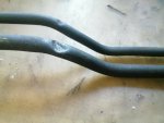
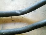
the kinked return pipe is normal, a lot of them had it. I think it was probably manufacturing "defect" which didn't cause any problems, other than our OCD hating it.
the front axle pivot is an interesting design, and it is often neglected, as two of mine were. One of them I had to physically disassemble the bearings and mower drive, remove all of that from the tractor and then spread the frame mounts enough to CUT the axle pivot completely off, as it was stuck like chuck. Once the axle was out of the chassis I was able to press (50 ton press....and it buried the gauge needle!) the remainder out of the axle, then had to go in and weld up the worn areas in the axle itself, remachine (mill) and FINALLY got to reassemble it all. The axle needs to be about .005 larger than the pivot tube, because if you try .000, it will seize pretty quickly and there's no place for grease to pass around the tube once you grease it-and it's wise to grease it OFTEN. Getting that part out was a test of my patience, believe me! My mom's got that mower now an it's been mostly fine other than a few years ago dad couldn't get it to start (didn't know how to bleed the system after running outta fuel), he hit it with the starting fluid and broke the ring lands out of the pistons. I rebuilt it last winter and mom's been using it since. It desperately needs power steering, and I have an EPS assembly from some old 4 wheeler but the problem is the lack of space to get the EPS to fit, ain't a lot of room under the dash. The G2160 is a little bigger in that area, for that reason (EPS fits).
On steering play most of the play I've seen is inside the steering gear assembly. You can pull it all apart and rebuild it, but I'm not sure how one can tighten up the slack in the splined shaft to sector gear slop. I tried to weld it (TIG) but the sector gear is made of something I'm not familiar with and I couldnt' get it to hold. I mean, it lasted a little while but finally broke loose while I was mowing, no big deal it just developed the "normal" slack in the steering again. Once you get it apart you'll see what I am talking about. I thought about maybe heating the sector up and letting it cool (shrinks it slightly) but because I was not familiar with the material, I didn't want to do that. I want to say it's powdered metal but I am not 100% positive. Have a look for yourself and keep us updated.
THe steering post has a rubber bushing at the top, which is supposed to reduce vibration from the 3 cylinder engine (all 3 cyl have a rocking couple that can sometimes be felt), and that rubber needs lube once in a while or the steering gets kinda odd feeling. Mom's was just worn out so I made some new UHMW bushings for it and put a grease fitting under the dash to get a little bit of lube in there once a year. One pump is all it needs, doesn't need to be sloppy just enough to put some lube in there--and keeping in mind, because of the radiant heat of the radiator, sometimes that grease (depending on the grease and the climate) will just fall out anyway. I did put a groove in the upper bushing that holds an o-ring but it won't completely solve it. Just something I do once a year, and she doesn't use the mower all that much anyway-about 35 hours a season, give or take. Small yard, under 1/2 acre total. She uses her Polaris for everything else as far as yard work. That little thing was a GREAT investment for her (well I actually bought it for her, but you get the idea). Couldn't pass it up for the money.

 332 KB Views: 152