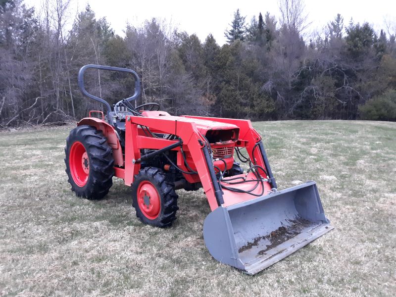
L295DT Hydraulic Lift Arms Non Functioning

jacksork

Member
Lifetime Member

Equipment
'79 L295DT
Apr 30, 2020
33
1
8
Vermont
1979 L295DT

Next on the list is the 3pt issue.

The hydraulic lift arms are dead. You can move them up or down, if you don't support them they just fall so if I am using the tractor for the FEL I just chain them up. The position lever has no resistance and neither do the arms. The draft lever has a little resistance but I don't see any effects when that lever is raised or lowered.

The question is I am not sure of the logical procession on where to start or necessarily how to troubleshoot what I would suspect are hydraulic issues in regards to the lifting arms.

Picture of the tractor because everyone likes pictures:
Front Starboard Side resized.jpg
 
Last edited:

Dave_eng

Well-known member
Lifetime Member

Equipment
M7040, Nuffield 465
Oct 6, 2012
5,145
941
113
Williamstown Ontario Canada
I am thinking that there is a hydraulic selector valve on your tractor. To direct hydraulic flow to the loader or the 3 pt. hitch.

I am guessing it would be close to where one of the loader hydraulic lines comes from.

Dave
 

North Idaho Wolfman

Moderator
Staff member
Lifetime Member

Equipment
L3450DT-GST, Woods FEL, B7100 HSD, FEL, 60" SB, 743 Bobcat with V2203, and more
Jun 9, 2013
29,039
5,357
113
Sandpoint, ID
If the three point lever doesn't have any resistance, it could be as simple as the connection (nuts) have come loose and you not actually moving the three point valve.
 

jacksork

Member
Lifetime Member

Equipment
'79 L295DT
Apr 30, 2020
33
1
8
Vermont
So would it be like an actual knob/switch?

From what I have gathered going through the Owners/Shop/Parts Manuals, it looks like I have the following options (names pulled from parts manual):
-Control Valve (looks to be connected to the position lever - possible suspect)
-Relief Valve (just for pressure relief so I would assume not a suspect)
-Draft Control Valve (connected to draft lever - possible suspect but less likely?)


I am thinking that there is a hydraulic selector valve on your tractor. To direct hydraulic flow to the loader or the 3 pt. hitch.

I am guessing it would be close to where one of the loader hydraulic lines comes from.

Dave
 

jacksork

Member
Lifetime Member

Equipment
'79 L295DT
Apr 30, 2020
33
1
8
Vermont
Externally it looks like everything is connected.

If I try to remove the hydraulic cylinder head (part name?) that the seat is bolted to and the control/draft/relief valves are attached to, should I drain the fluids first or can I remove it to look inside without draining?

If the three point lever doesn't have any resistance, it could be as simple as the connection (nuts) have come loose and you not actually moving the three point valve.
 

North Idaho Wolfman

Moderator
Staff member
Lifetime Member

Equipment
L3450DT-GST, Woods FEL, B7100 HSD, FEL, 60" SB, 743 Bobcat with V2203, and more
Jun 9, 2013
29,039
5,357
113
Sandpoint, ID
Pulling the cylinder and control valve is about step 20 in the troubleshooting and repair process.

Don't jump to that yet, besides there is very little you can repair in there, and that valve doesn't "just go out".

You first need to get the WSM, go to Kubotabooks.com and follow the troubleshooting guides.

If there is no resistance on the control lever something's not right, right there.

Do you know if you have hydraulic flow?

Is there a FEL attached?

HAve you turned the stop control under the seat?
 

jacksork

Member
Lifetime Member

Equipment
'79 L295DT
Apr 30, 2020
33
1
8
Vermont
I have the shop manual, the issue I have is of the 6 issues they list for troubleshooting, several of them seem applicable, and while there is some overlap, which one do you start with?

#1-Hitch will not lift....it won't stay up either
#2-Hitch will not raise fully....it doesn't lift at all
#3-Hitch will not lower....can't get it to raise for it to lower
#4-Hitch will not maintain position....can't get it to be in any position (raise/lower)
#5-Hydraulic system high pressure....I don't think this is it as the FEL functions
#6-Draft Control malfunction....possible but not the root issue I would think

Reading back through them as I write this, #4 seems like it may be the one to start with, which lists the possible causes as Hydraulic cylinder/piston; drop check valve in main control valve; and drop poppet valve in main control valve.

When you say hydraulic flow, hydraulic flow in general or to a specific location?

There is a FEL attached and that does function.

I have tried adjusting the control knob under the seat. No effects to the arms.


Pulling the cylinder and control valve is about step 20 in the troubleshooting and repair process.

Don't jump to that yet, besides there is very little you can repair in there, and that valve doesn't "just go out".

You first need to get the WSM, go to Kubotabooks.com and follow the troubleshooting guides.

If there is no resistance on the control lever something's not right, right there.

Do you know if you have hydraulic flow?

Is there a FEL attached?

HAve you turned the stop control under the seat?
 

Dave_eng

Well-known member
Lifetime Member

Equipment
M7040, Nuffield 465
Oct 6, 2012
5,145
941
113
Williamstown Ontario Canada
The knob under the seat will be to just adjust the lowering speed of the 3 pt arms.

Often on your vintage tractor there is a selector valve in the hydraulic circuit.

Loaders were not common and yet provision was made for external hydraulic circuits.

To switch between the 3 pt and the external circuits, such as a loader, there was a selector valve.

Trace the small pipe (high pressure) coming from the hydraulic pump. Trace the inlet hose from your loader valve backwards away from the loader valve.

The two should meet at the selector valve.

Dave
 

North Idaho Wolfman

Moderator
Staff member
Lifetime Member

Equipment
L3450DT-GST, Woods FEL, B7100 HSD, FEL, 60" SB, 743 Bobcat with V2203, and more
Jun 9, 2013
29,039
5,357
113
Sandpoint, ID
Is it a stock Kubota FEL?

If not, it's very likely that someone has it hooked up wrong and your not getting fluid flow or pressure to the three point valve.
 

jacksork

Member
Lifetime Member

Equipment
'79 L295DT
Apr 30, 2020
33
1
8
Vermont
Is it a stock Kubota FEL?

If not, it's very likely that someone has it hooked up wrong and your not getting fluid flow or pressure to the three point valve.
Not sure, it was painted at some point previously. Comparing it to pictures I have seen of L295DT's with stock loaders it looks very similar.
 

jacksork

Member
Lifetime Member

Equipment
'79 L295DT
Apr 30, 2020
33
1
8
Vermont
The high pressure pipe from the hydraulic pump goes directly to a port on the hydraulic cylinder cover. Port indicated with the red arrow.
Hydraulic Cover Port.jpg


What I am assuming is the input for the Loader valves comes from a tapped aluminum block mounted to the oil pressure block in lieu of the cover (referenced as #8/7 respectively in the diagram). Sidenote this model does not have the #10 flow priority valve.
Generic Hydraulic Valves-Linkage Diagram resized.jpg


I traced the hoses for the loader. Here is a sketch of that:
Loader Hose Diagram resized.jpg


Here is a picture of the actual loader levers. Why is there an extension on the side for the lift lever (left side)? Why is that different from the bucket lever?
Bucket Levers Resized.jpg
 
Last edited:

North Idaho Wolfman

Moderator
Staff member
Lifetime Member

Equipment
L3450DT-GST, Woods FEL, B7100 HSD, FEL, 60" SB, 743 Bobcat with V2203, and more
Jun 9, 2013
29,039
5,357
113
Sandpoint, ID
Crack the C and D line at the valve.
Without moving the valve you should get flow out of the D line.

The extra part a on the back of the lift spool is the detent section, it locks the loader valve into float.
 

jacksork

Member
Lifetime Member

Equipment
'79 L295DT
Apr 30, 2020
33
1
8
Vermont
Crack the C and D line at the valve.
Without moving the valve you should get flow out of the D line.

The extra part a on the back of the lift spool is the detent section, it locks the loader valve into float.
Am I understanding this correctly? Use a wrench and open up the hoses on the sides of the block at C/D? This is while the tractor is not running correct? Are they opened at the same time or one at a time?
 

North Idaho Wolfman

Moderator
Staff member
Lifetime Member

Equipment
L3450DT-GST, Woods FEL, B7100 HSD, FEL, 60" SB, 743 Bobcat with V2203, and more
Jun 9, 2013
29,039
5,357
113
Sandpoint, ID
Am I understanding this correctly? Use a wrench and open up the hoses on the sides of the block at C/D? This is while the tractor is not running correct? Are they opened at the same time or one at a time?
Yes, kind of, just crack the lines so they will leak, start it and observe which one leaks.
 

jacksork

Member
Lifetime Member

Equipment
'79 L295DT
Apr 30, 2020
33
1
8
Vermont
Question: The port that is marked OUT BYD, is that meant as the power beyond and should that be going back to the oil pressure block instead of the other hose at the 'C' location?

Update 8/23/2020; the OUT BYD is the power beyond and I think should just be plugged as I don't have another valve necessity at the moment but looking for confirmation on that.
 
Last edited:

Russell King

Well-known member

Equipment
L185F, Modern Ag Competitor 4’ shredder, Rhino tiller, rear dirt scoop
Jun 17, 2012
4,741
1,025
113
Austin, Texas
In tour diagram you don’t show a pump. It may be on front of the engine independent of the standard pump for the 3 point lift.

If so then you may not have any hydraulic pump working for the 3 point lift.

Please explain if you are sure where the front end loader gets it fluid from.
 

jacksork

Member
Lifetime Member

Equipment
'79 L295DT
Apr 30, 2020
33
1
8
Vermont
In tour diagram you don’t show a pump. It may be on front of the engine independent of the standard pump for the 3 point lift.

If so then you may not have any hydraulic pump working for the 3 point lift.

Please explain if you are sure where the front end loader gets it fluid from.
The loader get the hydraulic fluid via an aluminum block that replaces the cover to the oil pressure block (Post #11, picture #2, part #8).
 

jacksork

Member
Lifetime Member

Equipment
'79 L295DT
Apr 30, 2020
33
1
8
Vermont
Just pulled the rockshaft housing.

Helpful hint...If you have a ROPS, remove it, it made it so much easier to pull that housing off and out of the way. An engine hoist would have been a welcome addition (but not absolutely necessary) as well and have made its removal/relocation easier as well.

So here is what I found: The control arm "lever" (item #11 in post #11 2nd picture; also known as the spool drive lever in the parts manual) is missing. I drained the fluid and it is not anywhere in that reservoir. And the backup o-ring on the piston is torn. Everything else seems to be okay.
 
Last edited:

jacksork

Member
Lifetime Member

Equipment
'79 L295DT
Apr 30, 2020
33
1
8
Vermont
Update: Ordered a new lever, o-rings and gasket. Installed and now the 3pt will lift.....as long as it doesn't have a load on it. If you have a load on it, it won't lift it on it's own. If you have the 3pt with a load on it already in its up position (or anywhere above the minimum) and you lock the control knob it will stay where it is at, otherwise it will droop back down.

Fun fact: What is called the oil pressure block in the FSM is called the Hydraulic outlet in the Parts manual. It looks like the port to the front of the tractor is the high pressure side, and the port to the rear of the tractor is the low pressure.

So based on that the block has a high pressure and low pressure port, and it looks like it is correct as far supplying/receiving from the loader. However, am I correct in that the hose from the power beyond port on the loader valves to the reservoir tank is extraneous and should be removed? Would that cause an issue in regards to the 3pt?
 
Last edited: