I am putting an engine back together after a rod keeper failure. Pistons are back in Ready to put the head on and continue with flywheel clutch etc. Question is should I be doing some bench tests to check some things before I put the engine back in and Reconnect everything. Thanks for all the previous info, and thanks for any more info.
Kubota L35 putting back together.
- Thread starter Fluke216
- Start date
North Idaho Wolfman
Moderator
Staff member
Lifetime Member
Equipment
L3450DT-GST, Woods FEL, B7100 HSD, FEL, 60" SB, 743 Bobcat with V2203, and more
Just make sure you lined up all the timing marks on the front gears, it's by far the biggest mistake made.
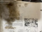
Ok yes I did have the timing cover off so I did that. Have a few questions putting the flywheel back on says about bring number 1 cylinder to tc ( top dead center). How do I know when the piston is at the top and is 1 cylinder at the water pump side? Ok I see that it is here in the manual.Just make sure you lined up all the timing marks on the front gears, it's by far the biggest mistake made.
also the valve clearance adjustment maybe attributed to the original faliure I think as the adjusting screw and nut were loose on that rocker arm above that push rod opposite where the keeper failed. Question is how do I get these all right part of the question is the same as the last as it mentions the piston at top dead center, then adjust with feeler gauge. Should lock tight be applied so they don’t come loose? Or I guess they should be checked periodically. I see it explains on how to do it but I’m slightly confused, or is there a different method I should use I don’t wanna screw it up ha. Ok thanks for any info
Ok yes I did have the timing cover off so I did that. Have a few questions putting the flywheel back on says about bring number 1 cylinder to tc ( top dead center). How do I know when the piston is at the top and is 1 cylinder at the water pump side? Ok I see that it is here in the manual.
also the valve clearance adjustment maybe attributed to the original faliure I think as the adjusting screw and nut were loose on that rocker arm above that push rod opposite where the keeper failed. Question is how do I get these all right part of the question is the same as the last as it mentions the piston at top dead center, then adjust with feeler gauge. Should lock tight be applied so they don’t come loose? Or I guess they should be checked periodically. I see it explains on how to do it but I’m slightly confused, or is there a different method I should use I don’t wanna screw it up ha. Ok thanks for any info
Attachments
-
 500.5 KB Views: 31
 -
 586.4 KB Views: 33
North Idaho Wolfman
Moderator
Staff member
Lifetime Member
Equipment
L3450DT-GST, Woods FEL, B7100 HSD, FEL, 60" SB, 743 Bobcat with V2203, and more
You don't need to bring it to TDC to put the flywheel on.
The flywheel only goes on one way, Just make sure all the bolts thread in by hand.
Do not use thread locker on the adjustment points on the rocker arms, you just use the nut to lock them down.
Loose rocker adjustments won't make an engine so south, it will just lose power, they don't get tighter when they loosen up.
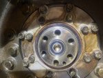
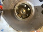
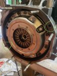
To me it looks like the flywheel could bolt on in any orientation. Or maybe the orientation doesn’t matter I was just thinking it needed to be on right in order to line the marks up in that window for what the manual said about adjusting valve clearance.You don't need to bring it to TDC to put the flywheel on.
The flywheel only goes on one way, Just make sure all the bolts thread in by hand.
Do not use thread locker on the adjustment points on the rocker arms, you just use the nut to lock them down.
Loose rocker adjustments won't make an engine so south, it will just lose power, they don't get tighter when they loosen up.
Attachments
-
 684.9 KB Views: 42
 -
 492.6 KB Views: 42
Line up the small hole on the crankshaft with the small circle “stain” on the flywheel and it will be back to original orientation.To me it looks like the flywheel could bolt on in any orientation. Or maybe the orientation doesn’t matter I was just thinking it needed to be on right in order to line the marks up in that window for what the manual said about adjusting valve clearance.
Ok so I spin the crank the exhaust rod goes up and comes down the the intake goes up and comes down and at that point the clearance should be adjusted for the respective cylinder that, that just occurred on and repeated the same way for the others. This is what I gathered from watching some videos does this sounds correct. ThanksYou don't need to bring it to TDC to put the flywheel on.
The flywheel only goes on one way, Just make sure all the bolts thread in by hand.
Do not use thread locker on the adjustment points on the rocker arms, you just use the nut to lock them down.
Loose rocker adjustments won't make an engine so south, it will just lose power, they don't get tighter when they loosen up.
North Idaho Wolfman
Moderator
Staff member
Lifetime Member
Equipment
L3450DT-GST, Woods FEL, B7100 HSD, FEL, 60" SB, 743 Bobcat with V2203, and more
While the holes look to be the same distance apart they are not, there is a difference in distance on one bolt hole, this is why it's critical to hand thread the bolts all the way in or you can cross thread them and damage the bolt and the crank.To me it looks like the flywheel could bolt on in any orientation. Or maybe the orientation doesn’t matter I was just thinking it needed to be on right in order to line the marks up in that window for what the manual said about adjusting valve clearance.
Put the flywheel on the crank not lined up with the small hole and the small hole mark and you will see one hole does not line up.
Yes you just need to make sure the cam lobe is not pushing the rocker up, it doesn't really matter where in the stroke it is as long as the pushrod and lifter are on the flats of the cam.
Thank you for that explanation. Makes sense I had put it on there when I saw the response from utterchaos and hand threaded all the bolts in. I did have it sitting up there before and yes a hole was slightly off . Ok I think I got it I reset them all the valve clearances the way I described in the explanation on how I thought it should be done.While the holes look to be the same distance apart they are not, there is a difference in distance on one bolt hole, this is why it's critical to hand thread the bolts all the way in or you can cross thread them and damage the bolt and the crank.
Put the flywheel on the crank not lined up with the small hole and the small hole mark and you will see one hole does not line up.
Yes you just need to make sure the cam lobe is not pushing the rocker up, it doesn't really matter where in the stroke it is as long as the pushrod and lifter are on the flats of the cam.
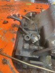
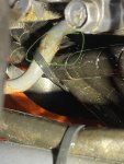
On another note does anyone know what these two wires are for and what they should be connected to they were not connected when I removed the panel frame.
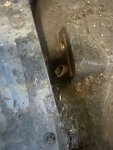
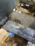
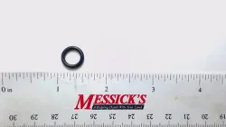
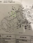
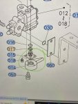
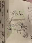
also one other dumb thing looking for any advice or comment. The front differential case has a pipe breather that snapped off. Pictures included I assume better just get another piece and replace. Or I could rig something up with a small rubber 90 and hose clamp.
anyway thanks for all the input guys.
Attachments
-
 497.8 KB Views: 35
 -
 307.7 KB Views: 32
 -
 415.6 KB Views: 31
 -
 479.6 KB Views: 30
North Idaho Wolfman
Moderator
Staff member
Lifetime Member
Equipment
L3450DT-GST, Woods FEL, B7100 HSD, FEL, 60" SB, 743 Bobcat with V2203, and more
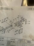
I would get a new one:

And 2 Orings
And 2 Orings
Ok thanks will do.I would get a new one:
And 2 Orings
I went to messicks today to get snap pins for the clutch holder. I inquired about the pipe breather I knew they didn’t stock it but there is 2 versions and the one is discontinued and he said the two are not compatible. So not sure what to do about that. Unless that’s incorrect as mine is the earlier one before the serial number break.I would get a new one:
And 2 Orings
On another note he said this was a hydraulic fluid that met super udt2 specs. https://viscosityoil.com/product/unitraction-transmission-hydraulic-fluid-coolsemi-synthetic/. not much cheaper though 129vs141 for a 5 gal.
one other thing I noticed when getting ready to mate the clutch housing back on one of the strait pins is missing, I’m pretty sure the last time someone had it off it was not reinstalled I’m assuming best practice to get a pin and install it unless for some reason it’s not critical. Ok thanks again for any and all info
Attachments
-
 496.4 KB Views: 30
 -
 550.1 KB Views: 30
 -
 835.3 KB Views: 27
North Idaho Wolfman
Moderator
Staff member
Lifetime Member
Equipment
L3450DT-GST, Woods FEL, B7100 HSD, FEL, 60" SB, 743 Bobcat with V2203, and more
I like all the alinement pins installed.
It will work without them but it allows parts to be misaligned.
It will work without them but it allows parts to be misaligned.
Ok thanks yes I got the Pin Got it bolted up and the machine back together got fuel out of lines and got it to fire up. So a problem and a few questions. The hydraulic regulator valve delivery pipe was bent before and I think I moved it some so now it has a hole in it messicks list the part number as 32751-66210 and says it’s discontinued is the pipe repairable?I think it’s made of copper? Not sureI like all the alinement pins installed.
It will work without them but it allows parts to be misaligned.
The manual says to bleed the power steering hoses after reconnecting, how is this done?
In my other post I couldn’t get the the u joint loose from the shuttle shift shaft and had to remove the roll pin in the bottom of it glove had it soaking in blaster since and I got it apart I marked it with a grinder so it would go back together right, but is there a way to make sure I have it set in the correct position.
One other question the throttle has a bolt apparatus governing it so it can’t be out all the way up is this how it came from the factory and should it be kept like that.
thanks for any and all info. Much appreciated
Attachments
-
 612.8 KB Views: 19
 -
 621.6 KB Views: 17
 -
 464 KB Views: 20
 -
 368.2 KB Views: 19
Last edited:
North Idaho Wolfman
Moderator
Staff member
Lifetime Member
Equipment
L3450DT-GST, Woods FEL, B7100 HSD, FEL, 60" SB, 743 Bobcat with V2203, and more
Steering will bleed itself.
Shuttle needs to be in neutral and keep the lever in neutral when you reassemble it.
That is a high pressure steel pipe, it needs to be tig welded or silver (hard) soldered.
Looks like all states might have one:

 www.tractorpartsasap.com
If you can
t get a new one, or don't have anyone that can fix it, you could send it to me and I can fix it for you.
Shuttle needs to be in neutral and keep the lever in neutral when you reassemble it.
That is a high pressure steel pipe, it needs to be tig welded or silver (hard) soldered.
Looks like all states might have one:
Used Delivery Pipe fits Kubota L35 L35 32751-66210
Delivery Pipe for Kubota Backhoe Loader(s) L35, Construction & Industrial(s) L35. Replaces Kubota OEM Number(s) 32751-66210.
www.tractorpartsasap.com
If you can
t get a new one, or don't have anyone that can fix it, you could send it to me and I can fix it for you.
Ok yea I was looking at their website last night I called them today but they said that part is gone. I’ll see if I can find someone to repair it the pipe is smashed somewhat from before so I think someone would almost have to remove a section and weld a section back in so you think that’s possible? Or maybe that hole can just we welded shut, let me know what you think. ThanksSteering will bleed itself.
Shuttle needs to be in neutral and keep the lever in neutral when you reassemble it.
That is a high pressure steel pipe, it needs to be tig welded or silver (hard) soldered.
Looks like all states might have one:
Used Delivery Pipe fits Kubota L35 L35 32751-66210
Delivery Pipe for Kubota Backhoe Loader(s) L35, Construction & Industrial(s) L35. Replaces Kubota OEM Number(s) 32751-66210.
If you can
t get a new one, or don't have anyone that can fix it, you could send it to me and I can fix it for you.