Converting my 5’ manual adjusted rear grading blade to hydraulically operated

Farmer Brian

New member

Equipment
B2301 & RTV 500
Jan 20, 2021
8
0
1
Fort Erie Ontario Canada
Has anyone one in orange land ever customized their rear manual adjusted grading blade to a hydraulic operation?
I have a 5’ blade on the 3point of a B2301, but a matching model is not as important as the parts and details of what it took to do the conversion.
image.jpg
 

NHSleddog

Well-known member
Lifetime Member

Equipment
B2650
Dec 19, 2019
2,149
1,831
113
Southern, NH
I did my rake/blade. I did mine with my son. It was a design/build.

rake1.jpg


rake3.jpg


rake4.jpg
 
  • Like
Reactions: 1 users

kubotasam

Well-known member

Equipment
B2410, B7100dt, B7500,Woods BH750,Landpride 2660RFM, Tiller, B2781 Snowblower
Apr 26, 2010
1,204
128
63
Alfred Maine
Here is how I converted by back blade to power angle. Don't know how much help it will be to you as my blade built much different than yours.
Cylinder, hoses and fittings from Surplus Center. The pins that the cylinder ends go on are implement pins for lower 3 point hitch arms from Tractor supply. Rest was scraps of steel I had.
Blade 1.jpg
Blade 2.jpg
Blade 4.jpg
Blade 3.jpg
 
  • Like
Reactions: 2 users

Ikc1990

Active member

Equipment
Kubota m125x, m9000, b2710, and other equiptment
Dec 2, 2020
292
130
43
Vermont
Nice job I like the added hook in back too. I thought of doing something like this and reinforcing the top of blade and putting s few chain slots for pulling a log or 2, and a basket or tool box on it for storage chains etc.
 

GordonE

New member

Equipment
BX2380
Jul 21, 2017
13
0
1
Carleton Place ont canada
Farmer Brian

I have added hydraulic swivel capability to my Landpride RB0560 .

Parts 4 x 9 x 3/8 steel plate Qty 2
1.25 x 3 inch steel rod Qty 1
1.5 bore x 12 inch stroke Prince Wolverine series cylinder
(Swivel eye at both ends)
Steel tube 0.75 id x ?? od x 3 inch lomg Qty 2
Various hydraulic hoses and fittings
Various linch pins

My setup was made so that I could use it in both forward and backward directions. The cylinder end at the scraper end is removed, blade rotated 180 degrees and reattached at other side.

4 x 9 plates are drilled with a 0.75 hole to match the cylinder swivel end holes. The Steel tube is welded on the bottom of the plate to align with the 0.75 hole to provide strength for the linch pin that holds the cylinder end. The location of the hole in the 4 x 9 plates has to align with the pivot point of the blade. The 4 x 9 plate was then welded to the bottom of the plow support.

1.25 x 3 steel rod was machined down to 0.75 for about 2.5 inch to match the
cylinder end swivel eye. A hole was drilled into the end for a small linch pin. This machined rod was welded to the tractor end of the RB0560.

Before actually welding I clamped all the pieces in place to make sure the blade would swivel plus and minus 30 degrees.

Good luck.

Pic6.jpg
Pic7.jpg
Pic7.jpg
Pic6.jpg
Pic5.jpg
Pic4.jpg
Pic3.jpg
Pic2.jpg
pic1.jpg
 

Ping

Active member

Equipment
BX2370-1
Dec 25, 2018
312
226
43
Troy, Ohio
Farmer,
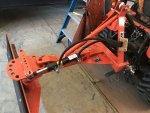
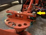
This is what I cobbled together for my rear blade. Allows me to rotate blade 180 deg by pulling the at the blade (the picture shows a threaded dowel pin i used for mock up). Somewhere i still have my 2D drawings for all the details if you're interested.
Regards.
 

Attachments

Farmer Brian

New member

Equipment
B2301 & RTV 500
Jan 20, 2021
8
0
1
Fort Erie Ontario Canada
Farmer,
This is what I cobbled together for my rear blade. Allows me to rotate blade 180 deg by pulling the at the blade (the picture shows a threaded dowel pin i used for mock up). Somewhere i still have my 2D drawings for all the details if you're interested.
Regards.
Love that set up, very neat job. Thanks a bunch
 

Ping

Active member

Equipment
BX2370-1
Dec 25, 2018
312
226
43
Troy, Ohio
Love that set up, very neat job. Thanks a bunch
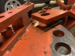
I would think that if you added ears to both sides of your pivot hole plate (orange) and a clevis mount cylinder (green) your modifications should turn out pretty clean and the hardware pretty easy to fab up too.
Inkedimage_LI.jpg
 

Farmer Brian

New member

Equipment
B2301 & RTV 500
Jan 20, 2021
8
0
1
Fort Erie Ontario Canada
Farmer,
This is what I cobbled together for my rear blade. Allows me to rotate blade 180 deg by pulling the at the blade (the picture shows a threaded dowel pin i used for mock up). Somewhere i still have my 2D drawings for all the details if you're interested.
Regards.
Would love to see your 2d diagram on this conversion. I would like to be able to turn my blade 180 deg like you mentioned. I saw this on YouTube, it’s done with a hydraulic motor, chain and sprocket
 

Attachments

Ping

Active member

Equipment
BX2370-1
Dec 25, 2018
312
226
43
Troy, Ohio
Would love to see your 2d diagram on this conversion. I would like to be able to turn my blade 180 deg like you mentioned. I saw this on YouTube, it’s done with a hydraulic motor, chain and sprocket
I'd be happy to share but, I need to let you inside my head (that's scary) on my design process.
On my blade (its a King Kutter XB) I wanted to ability to go back to manual angle adjustment if I ever needed to. Read, if I had problems with the angle cylinder, hoses or rear remote valve, I didn't want that downtime from preventing me from moving snow.
My first plan was to do like I suggested to your blade (add a wing on either side of your rotation plate) with clevis mount cylinder. This is where mocking up the design with cardboard, plywood or whatever you have laying around is worth it's weight in gold. On my mockup, I found that the 'ears' short enough to clear the manual angle pin hole ( green arrow in attached picture) were too short for the clevis mount to pivot thru its range of motion if that makes sense. The areas of interference between the clevis mount and blade angle plate are shown in blue. This is what led me to stack the mounting blocks on the blade and use an swivel eye cylinder. The mounting blocks still clear everything and all that is needed to reverse the blade is to pull the pin (yellow arrow), rotate the blade 180 degrees and install pin on opposite hole.
Hope this makes sense.
For the hydraulic motor - chain setup you show, would be the cat's arse! It that would allow any angle your little heart desired without getting out of the seat. My only concern or caution and others are free to chime in would be that when pushing heavy snow, the blade would overpower the hydraulic motor and allow the blade to rotate. Also, I'm not sure what kind of havoc that would play with the rest of the hydraulics. If you calculate the foot-pounds of torque required for the motor to prevent reverse rotation that setup appears to be the cleanest.
Hope this helps and let me know if you still want 2d details. I've got them in CAD and can easily create .pdfs for you.
Regards
 

Attachments