Mike! Hold the presses! I think I just discovered something that could potentially destroy the turbo in your 2501 and your production kits!
It all started when I was looking for an oil outlet flange to fit the TD025. When I searched for "turbocharger oil outlet flange" I kept getting hits for "turbo oil inlet flange". This kept happening, and I would look at the TD025 and see that there was a threaded hole on the topside of turbo when mounted, and a large hole with two smaller mounting holes on the bottom side, like this:
View attachment 110120
View attachment 110121
It kept bugging me, like a pebble in my shoe: Why is it not called an oil outlet flange? Then, last night in the middle of the night, it hit me: OMG, I've been assuming that small hole on the top of the turbo was the oil inlet. IT'S NOT! THAT IS THE OIL OUTLET SIDE!
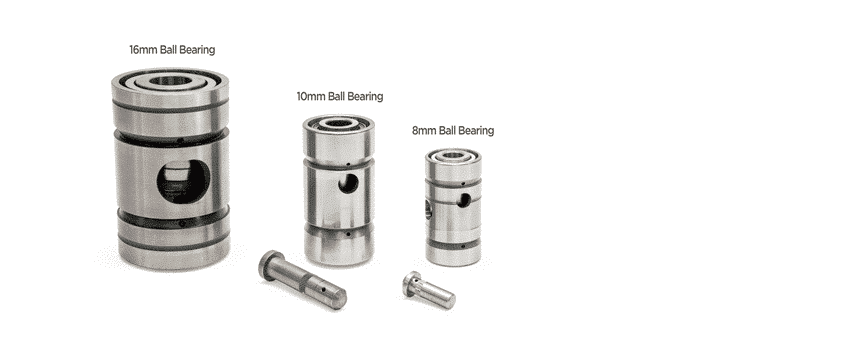
The idea is to pump oil into the turbo through the large bolt-on inlet flange on top and fill up the reservoir, while the outlet side with the small fitting drains it. Interestingly, when you look into that small bored outlet hole on the turbo, you see two small channels on the sides and one small hole directly in the center. I believe this may be to allow pressure to build up and flood the bearings (or bushings) in the turbo to keep things properly lubricated. Flipping the configuration around is an unknown situation that could potentially damage the turbocharger down the road. There are two different bearing types commonly used in turbochargers. Here is a good description of the two types and how they differ in operation:
The turbo bearing system may appear simple in design, with one or two bronze bearings, but it plays a key role. Ball Bearing turbo are vital.

www.garrettmotion.com
The Mitsubishi TD025 turbocharger used in our small Kubota tractors is of the journal bearing type, requiring sufficient, constant pressure to keep things lubricated, as described in this link to turbo oil supply and drain systems:
Article outlining the differences between a journal bearing turbocharger system and a ball bearing turbocharger system, as well as the oil drain systems employed in each with images accompanying to illustrate.

gcg.com.au
Curiously, almost all the oil inlet flanges advertised online have a very small orifice in them as well, which would tend to indicate that they are for ball bearing systems instead of journal bearings. One of these oil inlet flanges could still be used if you drill out the small orifice size to allow more oil flow to the inlet. It would make sense then, that the outlet side of the TD025 turbo DOES have a smaller orifice to facilitate keeping oil pressure up inside the reservoir and the journal bearings.
So why are the inlet and outlet ports flipped 180 degrees when you purchase an off-the-shelf TD025 turbo?
Apparently, a stock TD025, it is designed to HANG from an exhaust manifold instead of PERCH on top of the manifold because it was designed for a different application in small cars. This is obviously just backwards to what is needed in our Kubota's. So, how are you supposed to reposition the oil inlet and outlets?
This is achieved through a relatively common process called "clocking", and what it refers to (in a nutshell) is the relative axial position of the exhaust side of the turbocharger to the axial position of the compressor side. In other words, the exhaust side needs to be rotated in such a way as to align the oil inlet/outlet ports within +/-15 degrees of vertical, with the OIL INLET FLANGE ON TOP, and the compressor side rotated to optimize the tubing path from the turbo to the engine. Here is a video, albeit a little wonky, of how to clock a similar TD04 turbo:
Mike, you may want to research this yourself and give me your input. Is there something I overlooked or misunderstood? Let me know what you think. Thanks.
Solo


