I’m gonna chronicle in this post the installation of the Kubota OEM 3rd function on an L4760 HSTC tractor.
The printed instructions are in the Loader Assembly Instructions manual for a LA555/LA855/LA1055 loader - they do NOT come with the kit. Ask your dealer for the above document - the steps are in there. This is on a LA1055 - but it's almost the same, only real difference is the smaller loaders have 2 orange shims that come in the kit that go behind the solenoid.
There are basically 4 general groups of steps :
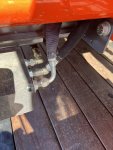
Here’s the guard mounted on the loader frame. It mounts behind it and will have the hard lines for the hydro connect through it. You can see the lines already in this pic. Those capped ends will attach to the power beyond and return lines that you plumb in later in group 3 steps.

This is how the lines go through. The lines get installed after this plate and the solenoid get installed. The big washer goes on the back of the plate then the nut on the fitting (not seen)

Here’s the solenoid. Note to install this - remove the step. Way easier since it's heavy and after you get it mounted you then have to mount the 2 hardlines shown in the above to pictures. Just a lot more room then. Also in this pic are the lines to the mounted connectors on the solenoid up to the QD block added to the loader behind the loader QD connections. The green and gray caps you see are the new ones. Also note here - the gray cap uses the gray hose to the rear most connection. That's in the instructions but this is apparently a place people mess up.

Here’s those lines entering an opening in the loader you have to open - there are 4 10mm bolts holding this plate on and an identical one at the bottom of the boom on the inside. You feed the 2 hoses down through the boom here and it's a little effort t opull the bend fitting out the bottom... you actaully stuff less hose in than you think and I found it suddenly very easy to pull them out the bottom when I adjsted how much was inside the boom so just the tips were able to be grabbed.

Here's the hoses coming out on the bottom front of the boom. And here’s the connector block on the front. To mount this I had to remove the guard plate it’s bolted to In order to get my bolts in. You will note - the 2 ends are DEAD HEADED... You must supply your own connectors. I'll be installing those at the end.

The printed instructions are in the Loader Assembly Instructions manual for a LA555/LA855/LA1055 loader - they do NOT come with the kit. Ask your dealer for the above document - the steps are in there. This is on a LA1055 - but it's almost the same, only real difference is the smaller loaders have 2 orange shims that come in the kit that go behind the solenoid.
There are basically 4 general groups of steps :
- Mount the guard and solenoid and piping
- Run the lines up the loader and mount the connector block on the loader
- Splice in the hydro lines and connect to the solenoid
- Swap the joystick and connect the new
Here’s the guard mounted on the loader frame. It mounts behind it and will have the hard lines for the hydro connect through it. You can see the lines already in this pic. Those capped ends will attach to the power beyond and return lines that you plumb in later in group 3 steps.
This is how the lines go through. The lines get installed after this plate and the solenoid get installed. The big washer goes on the back of the plate then the nut on the fitting (not seen)
Here’s the solenoid. Note to install this - remove the step. Way easier since it's heavy and after you get it mounted you then have to mount the 2 hardlines shown in the above to pictures. Just a lot more room then. Also in this pic are the lines to the mounted connectors on the solenoid up to the QD block added to the loader behind the loader QD connections. The green and gray caps you see are the new ones. Also note here - the gray cap uses the gray hose to the rear most connection. That's in the instructions but this is apparently a place people mess up.
Here’s those lines entering an opening in the loader you have to open - there are 4 10mm bolts holding this plate on and an identical one at the bottom of the boom on the inside. You feed the 2 hoses down through the boom here and it's a little effort t opull the bend fitting out the bottom... you actaully stuff less hose in than you think and I found it suddenly very easy to pull them out the bottom when I adjsted how much was inside the boom so just the tips were able to be grabbed.
Here's the hoses coming out on the bottom front of the boom. And here’s the connector block on the front. To mount this I had to remove the guard plate it’s bolted to In order to get my bolts in. You will note - the 2 ends are DEAD HEADED... You must supply your own connectors. I'll be installing those at the end.
Last edited:


