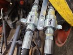
Power beyond port vs tank port

TheOldHokie

Well-known member
Lifetime Member

Equipment
L3901/LA525, B7200DT/B1630, G2160/RCK60, G2460/RCK60
Apr 6, 2021
8,772
4,507
113
Myersville, MD
windyridgefarm.us
Question for the obvious experts in this thread, on a related topic: The 3rd function valve I purchased does not have a PB port on it. Its P port connects to the PB port on my loader valve, and then the tank port connects back to the PB port on the tractor, which of course feeds the 3 point. I’ve looked at several 3rd function valves from various companies(Summit, WR Long, etc.) and they all seem to be configured this way. The valves don’t have a relief built in, and they don’t have a PB port. So the questions are 1. With the info noted earlier in this thread, shouldn’t these 3rd function valves have a PB port and relief valve? 2. If not, then why would a rear remote valve need to have a PB port & relief? What’s the difference? Can’t seem to find this answer anywhere. My ultimate goal is to add a rear valve to control a top link cylinder. I already have the electric 3rd function valve for my grapple. So I’m just trying to determine the type/configuration of the valve I’ll need to get for my rear cylinder. Thanks in advance for any advice.
The 3rd function valves are usually an industrial solenoid valve designed for subplate mounting. As such the valve only has a P and T port where the T port is rated for nearly the same pressure as the P port. That allows it to power a downstream device. It does not require a relief valve because that function is being provided by the subplate or a loader valve which is also being protected by the main relief in the tractors outlet block. Here is my 3rd function valve. It is a commodity monoblock with power beyond and inlet relief and is plumbed with a tank return and power beyond circuit. Also notice that this particular valve has 3 tank ports so you still have a top and side tank option when the power beyond plug is installed.

So why do you want a power beyond circuit? The primary answer is in Torch's explanation - the exhaust oil from the actuators (cylinder/motor) goes direct to tank not to the inlet side of a downstream device. This isolates the actuator from down stream loads. When you use the T port to power a downstream device you are putting the actuators on the upstream device in series with the ones on the downstream device - e.g. the output from your grapple cylinder is being used to extend the 3pt cylinder. This can cause unexpected movements of an actuator and possibly create dangerous control scenarios. It also creates the potential for pressure intensification in the rod ends of cylinders that the inlet over pressure relief cannot see and relieve causing cylinder rupture/blowout.

Dan

LA525AuxValve.png
 

TheOldHokie

Well-known member
Lifetime Member

Equipment
L3901/LA525, B7200DT/B1630, G2160/RCK60, G2460/RCK60
Apr 6, 2021
8,772
4,507
113
Myersville, MD
windyridgefarm.us
Hey Torch, Thanks for the quick reply. I have limited experience with hydraulics so I appreciate all your help.

You are correct, I am trying to connect to the hydraulic supply; basically insert the 3rd function into the sequence of valves (before or after the existing loader valves, doesn't matter to me).

Please confirm on my third photo: are you saying that the Orange Hose is the Power Beyond Port? (This is "Port B" shown in the manual on photo #1).

Thanks
The port on the loader valve labeled BY is the power beyond port. That hose should be moved to the T port on the 3rd function. A new hose should be used to connect the BY port on the loader valve to the P port on the third function.

Dan
 
  • Like
Reactions: 1 user

torch

Well-known member

Equipment
B7100HSD, B2789, B2550, B4672, 48" cultivator, homemade FEL and Cab
Jun 10, 2016
2,619
869
113
Muskoka, Ont.
As shown in the document I linked, the third function valve should be after the loader valve. As Wolfman shows in his diagram, the hose that used to go to the C port from the loader valve should go into the 3rd function P port and a hose run from the 3rd function T port should go to the C port.
 
  • Like
Reactions: 1 user

Mad Bubbler

New member

Equipment
Kubota MX5100 HST
Mar 18, 2015
26
0
1
Ontario, Canada
Are you running another valve after the WR Long Third function valve?
I'm talking about the valve with the star knob in the first picture.

Is that control part of the Motor control that your working with?
Hey Wolfman,

The valve with the star looking knob is a "switch valve" that when pushed in it controls a valve on the front of the loader (for a grapple thumb) or when pulled out it controls a valve on the rear (for snowblower chute rotation).


if i am reading your image correctly, i think your telling me I i just have my "P & T" hose crossed on the 3rd function kit. is that correct?
 

North Idaho Wolfman

Moderator
Staff member
Lifetime Member

Equipment
L3450DT-GST, Woods FEL, B7100 HSD, FEL, 60" SB, 743 Bobcat with V2203, and more
Jun 9, 2013
30,234
6,397
113
Sandpoint, ID
Hey Wolfman,
If I am reading your image correctly, I think your telling me I just have my "P & T" hose crossed on the 3rd function kit. is that correct?
Yes I do believe that is correct.
 
  • Like
Reactions: 1 user

TheOldHokie

Well-known member
Lifetime Member

Equipment
L3901/LA525, B7200DT/B1630, G2160/RCK60, G2460/RCK60
Apr 6, 2021
8,772
4,507
113
Myersville, MD
windyridgefarm.us
Are you running another valve after the WR Long Third function valve?
I'm talking about the valve with the star knob in the first picture.

Is that control part of the Motor control that your working with?
That looks like a three way selector valve.

Dan
Hey Wolfman,

The valve with the star looking knob is a "switch valve" that when pushed in it controls a valve on the front of the loader (for a grapple thumb) or when pulled out it controls a valve on the rear (for snowblower chute rotation).


if i am reading your image correctly, i think your telling me I i just have my "P & T" hose crossed on the 3rd function kit. is that correct?
I believe we had a discussion about that and the WR Long instructions .about a year ago The WR Long instructions had the connections reversed.

Dan
 
  • Like
Reactions: 1 user

Mad Bubbler

New member

Equipment
Kubota MX5100 HST
Mar 18, 2015
26
0
1
Ontario, Canada
That looks like a three way selector valve.

Dan

I believe we had a discussion about that and the WR Long instructions .about a year ago The WR Long instructions had the connections reversed.

Dan
That is possible, when i called W.R. Long this morning and sent them the same photos they said " everything looks correct". I got a weird vibe so i thought to post on here to see what kind of feedback i got.

I think you are correct that something is backwards, it just sucks that i have to blow gaskets on my bi-rotational pump to find out each time. lol

Once i get a new pump i will give it a test with the hoses switched. I will keep everyone posted how it goes.

I appreciate everyone's help on this issue.
You guys are great.
 

TheOldHokie

Well-known member
Lifetime Member

Equipment
L3901/LA525, B7200DT/B1630, G2160/RCK60, G2460/RCK60
Apr 6, 2021
8,772
4,507
113
Myersville, MD
windyridgefarm.us
That is possible, when i called W.R. Long this morning and sent them the same photos they said " everything looks correct". I got a weird vibe so i thought to post on here to see what kind of feedback i got.

I think you are correct that something is backwards, it just sucks that i have to blow gaskets on my bi-rotational pump to find out each time. lol

Once i get a new pump i will give it a test with the hoses switched. I will keep everyone posted how it goes.

I appreciate everyone's help on this issue.
You guys are great.
I dont think reversed connections at the 3rd function are related to blowing seals on your motor. Thay sounds more like you have the motor deadheaded Your picture of the loader and 3rd function plumbing looks fine. But that other stuff is a black box. An explanantion of it would be helpful in understanding what you are trying to do.

Dan
 
Last edited:
  • Like
Reactions: 1 user

North Idaho Wolfman

Moderator
Staff member
Lifetime Member

Equipment
L3450DT-GST, Woods FEL, B7100 HSD, FEL, 60" SB, 743 Bobcat with V2203, and more
Jun 9, 2013
30,234
6,397
113
Sandpoint, ID
Are you using a single third function valve to run a motor?
If you are it's not going to work, they do not operate like that.
The flow is to restricted.
You need a solenoid valve that is made for motor function.
 
  • Like
Reactions: 1 user

Mad Bubbler

New member

Equipment
Kubota MX5100 HST
Mar 18, 2015
26
0
1
Ontario, Canada
Are you using a single third function valve to run a motor?
If you are it's not going to work, they do not operate like that.
The flow is to restricted.
You need a solenoid valve that is made for motor function.

Basically what i am trying to do is i need 1 extra valve on the front of my tractor (to operate the grapple thumb) and I need 1 extra valve on the back of the tractor (to operate a snowblower chute rotator).
What i have done (or trying to do) is add a 3rd function kit (W.R.lONG) which will give me 1 extra set of ports at my loader valve. Then I have added a "valve switch" (the star looking handle) which gives me the ability to switch between 2 additional ports (one at the front, and one at the rear of the tractor).

The "motor" i speak of is a 12 GPM Bi-rotational hydraulic pump which i plan to mount which will operate the snow blower chute rotation gear. So basically when i use the 3rd function button it spins the bi-rotational pump forward or reverse.
 

Mad Bubbler

New member

Equipment
Kubota MX5100 HST
Mar 18, 2015
26
0
1
Ontario, Canada
I dont think reversed connections at the 3rd function are related to blowing seals on your motor. Thay sounds more like you have the motor deadheaded Your picture of the loader and 3rd function plumbing looks fine. But that other stuff is a black box. An explanantion of it would be helpful in understanding what you are trying to do.

Dan

what do you mean by "motor deadhead"?

that black box with the star shape handle is a "valve switch" i bought from Tractor Innovations.
here is the link to the website.


TheOldHokie

Well-known member
Lifetime Member

Equipment
L3901/LA525, B7200DT/B1630, G2160/RCK60, G2460/RCK60
Apr 6, 2021
8,772
4,507
113
Myersville, MD
windyridgefarm.us
what do you mean by "motor deadhead"?

that black box with the star shape handle is a "valve switch" i bought from Tractor Innovations.
here is the link to the website.

I am familiar with that rig and it is a lot more complicated than need be. Technically it is a 6 way diverter. It is designed to switch one of the spools on the loader valve between two sets of cylinders - e.g loader bucket circuit and rear remotes. Its a really poor way to add remotes to a tractor. If you are blowing seals I suspect you have it plumbed incorrectly.. Even if plumbed correctly and you are trying to use the bucket spool to rrun the motor you have a different problem. The bucket spool probably has a regenerative circuit for fast dump and when you hook that up to a motor/pump you dead head it - e,.g apply full pressure to both ports on the motor/pump. That could easily be the cause of your blown seals.

All you need for the motor is another directional control valve like the one in my picture. Plumb it into the PB circuit after the 3rd function and use the work ports to control a set of rear quick connects for your motor.. it is always hot and no need to switch anything.

Alternatively install another solenoid valve on the rear., plumb it into the PB circuit, and use the ports on it to run the motor. Then you can use a simple center off SPDT switch up front to rotate the chute. Again always hot and no need to switch anything.

Dan
 
Last edited:

Mad Bubbler

New member

Equipment
Kubota MX5100 HST
Mar 18, 2015
26
0
1
Ontario, Canada
Yes that valve switch is marketed to be incorporated with the existing loader features, but instead if that set up, I installed the 3rd function kit so the switch valve is stand alone.

Tonight I am going to run a test with no ends on the hoses connected to the switch valve and 3rd function kit to see if fluid can flow out in its current configuration. If not, then I will swap the "C" ports as mentioned above and then run the same test. If I still can't get fluid to flow, then it is back to the drawing board for me.

I will keep everyone posted.
Thanks again for all the feedback and quick replies.
 

TheOldHokie

Well-known member
Lifetime Member

Equipment
L3901/LA525, B7200DT/B1630, G2160/RCK60, G2460/RCK60
Apr 6, 2021
8,772
4,507
113
Myersville, MD
windyridgefarm.us
Yes that valve switch is marketed to be incorporated with the existing loader features, but instead if that set up, I installed the 3rd function kit so the switch valve is stand alone.

Tonight I am going to run a test with no ends on the hoses connected to the switch valve and 3rd function kit to see if fluid can flow out in its current configuration. If not, then I will swap the "C" ports as mentioned above and then run the same test. If I still can't get fluid to flow, then it is back to the drawing board for me.

I will keep everyone posted.
Thanks again for all the feedback and quick replies.
How can the "switch valve" be used standalone? What is it switching and how? It only has two positions. Are you trying to use it as a directional control valve for the motor or do you have yet another valve for that? I think your problem is in those circuits and not in the loader or third function valve.

Dan
 

Mad Bubbler

New member

Equipment
Kubota MX5100 HST
Mar 18, 2015
26
0
1
Ontario, Canada
Ok, so I just ran a test with no hose ends in the existing configuration. I had fluid flowing through 1 hose. In The attached photo the "out" arrow pumped fluid no problem.

I then swapped the hoses on the 3rd function kit and basically I had the same result but the fluid came from the opposite hose. I assume this makes sense because you can't have fluid flow from both hoses until the system is a closed loop and full of liquid (right?).

So now I am wondering. Is it possible that when the bi-rotational pump blew the first time it was because I held the suction bottom instead of the flow button until the system was full of fluid?

Would that cause a gasket rupture?
 

Attachments

TheOldHokie

Well-known member
Lifetime Member

Equipment
L3901/LA525, B7200DT/B1630, G2160/RCK60, G2460/RCK60
Apr 6, 2021
8,772
4,507
113
Myersville, MD
windyridgefarm.us
Ok, so I just ran a test with no hose ends in the existing configuration. I had fluid flowing through 1 hose. In The attached photo the "out" arrow pumped fluid no problem.

I then swapped the hoses on the 3rd function kit and basically I had the same result but the fluid came from the opposite hose. I assume this makes sense because you can't have fluid flow from both hoses until the system is a closed loop and full of liquid (right?).

So now I am wondering. Is it possible that when the bi-rotational pump blew the first time it was because I held the suction bottom instead of the flow button until the system was full of fluid?

Would that cause a gasket rupture?
Until you tell me how that selector valve is plumbed I cannot answer those questions. It has six ports organized into three sets of two each. One set is flow in/out. The other two sets are switched back and forth between the first set when the spool is shifted. So lets start with what you have connected to the first set and work from there.

Dan
 

Mad Bubbler

New member

Equipment
Kubota MX5100 HST
Mar 18, 2015
26
0
1
Ontario, Canada
Until you tell me how that selector valve is plumbed I cannot answer those questions. It has six ports organized into three sets of two each. One set is flow in/out. The other two sets are switched back and forth between the first set when the spool is shifted. So lets start with what you have connected to the first set and work from there.

Dan
Here is a sketch of the switch valve operations and set up.
16443607515981075162225478272398.jpg
 

Mad Bubbler

New member

Equipment
Kubota MX5100 HST
Mar 18, 2015
26
0
1
Ontario, Canada
Until you tell me how that selector valve is plumbed I cannot answer those questions. It has six ports organized into three sets of two each. One set is flow in/out. The other two sets are switched back and forth between the first set when the spool is shifted. So lets start with what you have connected to the first set and work from there.

Dan
Here is a full sketch of the full hydraulic system. Let me knownif you need more information. I can get you whatever you need.
20220208_180704.jpg
 

TheOldHokie

Well-known member
Lifetime Member

Equipment
L3901/LA525, B7200DT/B1630, G2160/RCK60, G2460/RCK60
Apr 6, 2021
8,772
4,507
113
Myersville, MD
windyridgefarm.us
Here is a sketch of the switch valve operations and set up. View attachment 74681
OK - it appears you want to use the selector to switch the 3rd function valve between the grapple cylinders and the rear outlets. That is fine.

The lines going to the third function should be connected to the cylinder ports .
The lines labeled front hoses should be connected to the grapple cylinders.
The lines labeled back hoses shoudl be connected to the motor ports

Is that how you have it plumbed and are you 100% POSITIVE you have the third function work ports connected to the source ports on the selector valve?

If so you when the spool on the selector valve spool is moved to select the rear outlets you should; get flow out of one one rear hose when you press one of the joystick buttons and flow out of the other rear hose when you push the other button. When the spool is moved to the other position pressing one button should open the grapple and pressing the other should close it.

Edit: Just saw your sketch. If the valve does not operate as I described in the previous paragraph you have the ports on the selector valve mixed up. Here is what I would expect the porting to look like. You appear to have A and C reversed.

Dan
DV90-Instruction-Diagram[1].png
 
Last edited: