Testing fuel pump delivery - Bosch K type

JohnDB

Active member
Lifetime Member

Equipment
M4500DT
Jun 9, 2018
396
71
28
NZ
My S2600 WSM refers to a "Fuel tightness of pump element" test

Has anyone done one of these tests of a Bosch/Diesel Kiki K type injection pump? The purpose of the test is to find out if each element of the fuel injection pump is delivering appropriate pressure to the injector line, without having to pull the pump off the engine.

The way it is described in my WSM, if I follow the instructions, it looks like I will get hydraulic lock which could destroy something. :eek:

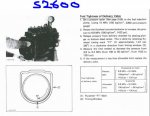
A screenshot of the manual is below, but in summary the process Kubota says to follow is:

* Attach a 30 MPa (4500 psi) gauge via a 600mm long fuel line to the delivery valve holder (there's a drawing of the gauge and line on another page also attached below).
* Set the throttle at idle.
* Turn the engine over on the starter (the injector lines are removed, so it won't start).
* If the pressure exceeds 14.7 MPa/2133psi, then that element is good.

(The manual also describes a separate process for testing the delivery valve fuel tightness like those below - and it involves hand turning the flywheel, not cranking over using the starter.)

Other manuals for engines using what I guess is the same sort of pump recommend a process that doesn't rely on cranking on the starter motor. E.g. Kubota 68mm stroke engines:
Their instruction is basically as above, but instead of using the starter motor, turn the flywheel counterclockwise, presumably by hand. Also looked at engines with similar pumps. None say to use the starter to crank over. Instead they recommend hand turning the engine counterclockwise, and if the pressure doesn't get to a certain level, then the element is bad.

See image below.

So if you've managed to read this far, would you mind advising me, :confused: is my S2600 manual wrong, and instead of cranking with the starter motor, I should use the process in the 68mm stroke engine manual? Thank you all.

(BTW I'm looking at doing this test because the engine note is uneven under load, I think I've covered all other factors for troubleshooting - injectors rebuilt, checked compression, done leakdown test, checked valve clearances etc etc, but I don't want to pull the pump off and send it for testing if it is actually OK).
 

Attachments

Last edited:

JerryMT

Active member

Equipment
Kubota M4500, NH TD95D,Ford 4610
Jun 17, 2017
528
156
43
The Palouse - North Idaho
My S2600 WSM refers to a "Fuel tightness of pump element" test

Has anyone done one of these tests of a Bosch/Diesel Kiki K type injection pump? The purpose of the test is to find out if each element of the fuel injection pump is delivering appropriate pressure to the injector line, without having to pull the pump off the engine.

The way it is described in my WSM, if I follow the instructions, it looks like I will get hydraulic lock which could destroy something. :eek:

A screenshot of the manual is below, but in summary the process Kubota says to follow is:

* Attach a 30 MPa (4500 psi) gauge via a 600mm long fuel line to the delivery valve holder (there's a drawing of the gauge and line on another page also attached below).
* Set the throttle at idle.
* Turn the engine over on the starter (the injector lines are removed, so it won't start).
* If the pressure exceeds 14.7 MPa/2133psi, then that element is good.

(The manual also describes a separate process for testing the delivery valve fuel tightness like those below - and it involves hand turning the flywheel, not cranking over using the starter.)

Other manuals for engines using what I guess is the same sort of pump recommend a process that doesn't rely on cranking on the starter motor. E.g. Kubota 68mm stroke engines:
Their instruction is basically as above, but instead of using the starter motor, turn the flywheel counterclockwise, presumably by hand. Also looked at engines with similar pumps. None say to use the starter to crank over. Instead they recommend hand turning the engine counterclockwise, and if the pressure doesn't get to a certain level, then the element is bad.

See image below.

So if you've managed to read this far, would you mind advising me, :confused: is my S2600 manual wrong, and instead of cranking with the starter motor, I should use the process in the 68mm stroke engine manual? Thank you all.

(BTW I'm looking at doing this test because the engine note is uneven under load, I think I've covered all other factors for troubleshooting - injectors rebuilt, checked compression, done leakdown test, checked valve clearances etc etc, but I don't want to pull the pump off and send it for testing if it is actually OK).
I have a M4500 with the S2600 engine and my workshop manual has different instructions. There is an instruction for "Fuel Tightness of fuel injection plunger" and one for "Fuel tightness of fuel injection pump delivery valve" . In my manual, these tests are conducted with the engine removed from the tractor and the engine rotated by hand. The tests consists of measuring the time for the pressure to drop from a specified high pressure to a specified lower pressure. The pass/fail instruction is "If the measurement is not acceptable replace …….." There is no acceptable time given for these pressure drop intervals. This is typical Kubota WSM bull crap! I have never seen poorer service information from any other tractor manufacturer!

The instruction that you refer to seems to be intended for the engine installed in the tractor A pressure of 2133 psig is not going to hurt anything in in the pump since the pump pressures are much higher during operation the pump plunger test in my manual specifies a high pressure for this Test at 8532 psig and a low of 7117 psig.

Do you have the pump spec's and the cam profile for bench tests?

I don't have the instructions in my manual that you have described, and though my WSM came from a Kubota dealer (Messsick's) in 2017 there is no Manual number or date noted anywhere in it except that it is 2003 reprint with Code No. 97897-10810.

Sorry I can't be of more help. Do you have a Kubota dealer near you that you can ask for help? Otherwise you will have to take the pump off and send it in for testing.
 

JohnDB

Active member
Lifetime Member

Equipment
M4500DT
Jun 9, 2018
396
71
28
NZ
Hi JerryMT, thanks for looking into this!

Manuals:
The engine manual I have is for the "B" version of the engine (S2200-B, S2600-B, S2800-B, code no. 97897-00771, October 1983). My WSM for the tractor (January 1983) specifies that the engine WSM is code 07909-70070 which covers a range of engines including the S2200-B and S2600-B and doesn't reference the -A variant, so I'm assuming my manual is still relevant, but yours must be a later version and by then Kubota had figured out a better process for testing the pump element, and put it in your manual.

So I think you've answered my question about the process, I won't use the pump element tightness test that's in my manual.

I often find it's useful to see more than one manual (errors etc) so if you want to look at the full manual that I've got, it's exactly the same as the Nanni Diesel version (Nanni diesel MA_6280HE_EN.pdf) that's on the net. Or if you can't find it, PM me.

Pressure drop time:
Your point about the time for pressure to drop not being in your manual: in my manual it's given as 10 seconds new, 5 seconds is the allowable limit, hope that's useful. See image below.

Pump specs:
I have what's in the manual, see image, but if you have something different or additional please tell me in case there's another error.

Local dealer:
The dealer is OK, but I try not to involve them unless absolutely crucial, I don't want them to think I'm a pest.

Again thanks for your help and I'd be interested in any other comments.
 

Attachments

Last edited:

JerryMT

Active member

Equipment
Kubota M4500, NH TD95D,Ford 4610
Jun 17, 2017
528
156
43
The Palouse - North Idaho
Hi JerryMT, thanks for looking into this!

Manuals:
The engine manual I have is for the "B" version of the engine (S2200-B, S2600-B, S2800-B, code no. 97897-00771, October 1983). My WSM for the tractor (January 1983) specifies that the engine WSM is code 07909-70070 which covers a range of engines including the S2200-B and S2600-B and doesn't reference the -A variant, so I'm assuming my manual is still relevant, but yours must be a later version and by then Kubota had figured out a better process for testing the pump element, and put it in your manual.

So I think you've answered my question about the process, I won't use the pump element tightness test that's in my manual.

I often find it's useful to see more than one manual (errors etc) so if you want to look at the full manual that I've got, it's exactly the same as the Nanni Diesel version (Nanni diesel MA_6280HE_EN.pdf) that's on the net. Or if you can't find it, PM me.

Pressure drop time:
Your point about the time for pressure to drop not being in your manual: in my manual it's given as 10 seconds new, 5 seconds is the allowable limit, hope that's useful. See image below.

Pump specs:
I have what's in the manual, see image, but if you have something different or additional please tell me in case there's another error.

Local dealer:
The dealer is OK, but I try not to involve them unless absolutely crucial, I don't want them to think I'm a pest.

Again thanks for your help and I'd be interested in any other comments.
John, the test conditions and the cam profile are identical. In the "adjustment of injection" panel at rack position 9 the amount of injection is 23 +/- 1.5 mm^3/st. In your manual the +/- is 0.5
 

JohnDB

Active member
Lifetime Member

Equipment
M4500DT
Jun 9, 2018
396
71
28
NZ
John, the test conditions and the cam profile are identical. In the "adjustment of injection" panel at rack position 9 the amount of injection is 23 +/- 1.5 mm^3/st. In your manual the +/- is 0.5
Thanks for that.

I assume each element needs to be calibrated so they are delivering the same amount - what physically is done to the pump or each element to do this? Or is it simply a matter swapping out old "out of spec" for new, on the assumption that say 6 new elements will always deliver the right amount?
 

North Idaho Wolfman

Moderator
Staff member
Lifetime Member

Equipment
L3450DT-GST, Woods FEL, B7100 HSD, FEL, 60" SB, 743 Bobcat with V2203, and more
Jun 9, 2013
30,563
6,607
113
Sandpoint, ID
There are different thickness of shims installed under the springs to set the pumps to the right spring timing.
There is also a internal set of adjustments on the valve body to time the flow of each delivery valve, but adjusting the timing to the cam.

These sorts of adjustments are best left to someone that has a complete setup of test equipment to properly monitor, measure and calibrate the pump completely.

Any chance you have a local diesel injection shop you can take it to?
 

JohnDB

Active member
Lifetime Member

Equipment
M4500DT
Jun 9, 2018
396
71
28
NZ
Thanks for the explanation Wolfman, I wondered about the shims - they are shown in the parts book but because there was 6, all with the same part number, I thought maybe they were merely a fixed spacer, rather than for adjustment. So from what you are saying, the shop adds to or removes the number of shims as required.

Yes, there's a local diesel injection shop I can take it to, they did the nozzles a year ago and I was happy with what they did. However I thought if I could do the external leak tightness checks myself first, if it checked out OK on those tests it would save me pulling the pump out unnecessarily. I try to disturb these things as little as possible.
 

JohnDB

Active member
Lifetime Member

Equipment
M4500DT
Jun 9, 2018
396
71
28
NZ
... In my manual ... the pass/fail instruction is "If the measurement is not acceptable replace …….." There is no acceptable time given for these pressure drop intervals.
This might be the answer... if your manual is like the 70 series stroke WSM, the time spec is in a different section of the manual - for the 70mm stroke series it is in the SG section. Example image below. Maybe your missing time spec is there in your manual too.

my manual specifies a high pressure for this test at 8532 psig and a low of 7117 psig.
That seems a high pressure compared with the other manuals I've browsed. I wonder if Messicks sent you the right manual?
 

Attachments

JerryMT

Active member

Equipment
Kubota M4500, NH TD95D,Ford 4610
Jun 17, 2017
528
156
43
The Palouse - North Idaho
This might be the answer... if your manual is like the 70 series stroke WSM, the time spec is in a different section of the manual - for the 70mm stroke series it is in the SG section. Example image below. Maybe your missing time spec is there in your manual too.


That seems a high pressure compared with the other manuals I've browsed. I wonder if Messicks sent you the right manual?
My WSM states it is for the M4000DT, M4500DT, M5500DT, M6500DT, and M7500DT. My tractor is a M4500( its a 2WD) but uses the same engine as the M4500DT. Here's the instructions for the "Fuel tightness of the fuel injection pump plunger (S2200, S2600):

1) Attach the pressure gauge
2) Rotate the flywheel to increase pressure to 8532 psig
3)Align the plunger with the Top Dead Center.
4)Measure the time needed to decrease the initial pressure from 8532 psig to 7110 psig
5) If the measurement is not acceptable, replace the pump element. In this case ask a repair shop to do the replacement. Be sure to give them adjustment reference data on the fuel injection pump. (Shown right)(These were the numbers with the cam profile that we talked about in a previous post. )

The actual article gives the pressure in MP's( 58.8- 49.0), as well as Kg/cm^2 (600 - 500)but I just used the psig numbers quoted.
 
Last edited:

JohnDB

Active member
Lifetime Member

Equipment
M4500DT
Jun 9, 2018
396
71
28
NZ
Thank you Jerry.

I can't help wondering why your manual quotes much higher pressures for testing than other manuals do for those K-type pumps, must be a recent development.
 

JerryMT

Active member

Equipment
Kubota M4500, NH TD95D,Ford 4610
Jun 17, 2017
528
156
43
The Palouse - North Idaho
Thank you Jerry.

I can't help wondering why your manual quotes much higher pressures for testing than other manuals do for those K-type pumps, must be a recent development.
It is strange especially when the injection pressures are on the order of 2000 psi.
 

JohnDB

Active member
Lifetime Member

Equipment
M4500DT
Jun 9, 2018
396
71
28
NZ
Could the higher pressure be related to the DI versions I believe there are of the S2600? (S2602, S2802 etc ?).

Update: S2602 like in the M4030, S2802 in the M5030. Some of the Kubota DI engine variants like the V1702 quote the same fuel tightness pressure specs as yours. So I'm picking that you have a DI engine manual. The pressure drops are 8 seconds new, 4 seconds service limit. If your M4500 has the standard S2600 IDI engine, Messicks may have sold you the wrong manual.
 
Last edited:

JerryMT

Active member

Equipment
Kubota M4500, NH TD95D,Ford 4610
Jun 17, 2017
528
156
43
The Palouse - North Idaho
Could the higher pressure be related to the DI versions I believe there are of the S2600? (S2602, S2802 etc ?).

Update: S2602 like in the M4030, S2802 in the M5030. Some of the Kubota DI engine variants like the V1702 quote the same fuel tightness pressure specs as yours. So I'm picking that you have a DI engine manual. The pressure drops are 8 seconds new, 4 seconds service limit. If your M4500 has the standard S2600 IDI engine, Messicks may have sold you the wrong manual.
Well the front page of the manual says M4500 DT among others and the internal reference are to the S2600 engine as well as other engine. So I don't think that's it.

However after thinking about it a bit, ff you consider that the injection pump element is connected to the fuel nozzle that is spring loaded to open at a certain pressure and also closes at a lower pressure Then the fuel element is either dead headed when the fuel injector is closed and then is providing fuel flow when the nozzle opens. Then it's possible for the instantaneous fuel pressures in the fuel element can get very high since the fuel is virtually incompressible. The pressure in the fuel element falls quickly when the nozzle opens to deliver the proper amount of fuel. The excess fuel delivered by the fuel element goes to leakage and bypass flow. The leak down test is required to assure that fuel element leakage is not excessive so that fuel delivered to the engine is metered properly. The higher the engine speed, the higher the fuel pressures have to be to deliver the increased fuel over the injection duration. So I think it is possible for the pressures to be quite high especially at high speed and load.

I hope this is making sense.
 
Last edited:

JohnDB

Active member
Lifetime Member

Equipment
M4500DT
Jun 9, 2018
396
71
28
NZ
JerryMT, what you say is logical. I guess after a few years Kubota decided on a different pressure test, i.e. the one mentioned in your manual. Did you ever find the acceptable duration for the pressure to drop from 8532 psi to 7110?
 

JerryMT

Active member

Equipment
Kubota M4500, NH TD95D,Ford 4610
Jun 17, 2017
528
156
43
The Palouse - North Idaho
JerryMT, what you say is logical. I guess after a few years Kubota decided on a different pressure test, i.e. the one mentioned in your manual. Did you ever find the acceptable duration for the pressure to drop from 8532 psi to 7110?
Yes I did. They were on the opposite page. My bad!

The reference leak down time is 8 sec and the acceptable says "4 sec or less". That' nonsense. It should say "between 8 Seconds and 4 seconds never less tah 4 seconds!

Since the fuel element is deadheaded to the pressure gauge I can see achieving these test pressures because there is no relief within the gauge. I wonder how steady one could hold it to do the leak down since any slight motion would either raise or lower the pressure. The bulk modulus (dPressure/dVolume) of the fluid is really high so a minute change in volume would be a big change in pressure. Perhaps they did some sort of correlation that allowed them to use the lower pressure to get acceptable results.

Additionally, you should not have to remove the engine to test the pump. That's pretty silly in my opinion. Can you put a breaker bar and socket on the crank shaft and rotate the motor?

The only way to get an answer to your questions is to talk to a pump shop that is familiar with this pump.

I worked with the Japanese on some aircraft programs and they have a good understanding of the engineering principles and they are very good at recognizing good ideas and they don't a have a high NIH (Not Invented Here). They recognize a good idea and immediately set to improve on it. This is how they learn and they become quite inventive. We had to watch ourselves not to give away trade secrets. The other weakness I see is they do not have any idea how Americans and Canadians, etc, other westerners use their farm equipment. Most of us try to fix things ourselves. Over there I guess they buy a new one.
 
Last edited:

JohnDB

Active member
Lifetime Member

Equipment
M4500DT
Jun 9, 2018
396
71
28
NZ
Jerry, good to hear that you found the time spec.

Since the fuel element is deadheaded to the pressure gauge I can see achieving these test pressures because there is no relief within the gauge. I wonder how steady one could hold it to do the leak down since any slight motion would either raise or lower the pressure.
The delivery valve test means holding steady is unnecessary - in the manuals I've seen Kubota says to bring it up to pressure then immediately back the crank off 90 degrees to see how well the valve holds the pressure.

And if the rated pressure isn't achieved after cranking over a several times then the element is stuffed.

Additionally, you should not have to remove the engine to test the pump. That's pretty silly in my opinion. Can you put a breaker bar and socket on the crank shaft and rotate the motor?
I don't think they were recommending removing the engine :) that photo was just for illustration. Remove front panel (grille, front cover, whatever it's called), easy access below the radiator to 36mm hex nut on the crank pulley.

The only way to get an answer to your questions is to talk to a pump shop that is familiar with this pump.
Their standard recommendation is to bring the pump in to put on their test bench and see for themselves, and I don't blame them. My thinking was how do they replicate the profile of the cam drive in the engine? And if I can test the pump myself it may answer the question as to whether it needs to be removed in the first place.

I worked with the Japanese on some aircraft programs and they have a good understanding of the engineering principles and they are very good at recognizing good ideas and they don't a have a high NIH (Not Invented Here). They recognize a good idea and immediately set to improve on it. This is how they learn and they become quite inventive. We had to watch ourselves not to give away trade secrets. The other weakness I see is they do not have any idea how Americans and Canadians, etc, other westerners use their farm equipment. Most of us try to fix things ourselves. Over there I guess they buy a new one.
Yes I've heard similarly. What was your role in aircraft program?
 

JerryMT

Active member

Equipment
Kubota M4500, NH TD95D,Ford 4610
Jun 17, 2017
528
156
43
The Palouse - North Idaho
Jerry, good to hear that you found the time spec.


The delivery valve test means holding steady is unnecessary - in the manuals I've seen Kubota says to bring it up to pressure then immediately back the crank off 90 degrees to see how well the valve holds the pressure.

And if the rated pressure isn't achieved after cranking over a several times then the element is stuffed.


I don't think they were recommending removing the engine :) that photo was just for illustration. Remove front panel (grille, front cover, whatever it's called), easy access below the radiator to 36mm hex nut on the crank pulley.


Their standard recommendation is to bring the pump in to put on their test bench and see for themselves, and I don't blame them. My thinking was how do they replicate the profile of the cam drive in the engine? And if I can test the pump myself it may answer the question as to whether it needs to be removed in the first place.


Yes I've heard similarly. What was your role in aircraft program?


I had various roles on programs with the 727, 737, SST, 757, 7J7, 777, HSCT, 737NG plus a few that never made it into production. I was a propulsion engineer (Nacelle Aerodynamics) and retired after 35 years as Propulsion Chief Engineer for Research and Preliminary Design. I was also a member of the Propulsion Advisory Committee to NASA Aeronautics Branch.


I thought we were talking about the fuel plunger test, because that required the very high pressures. Unless the system has a check valve in it to hold pressure, backing off on the flywheel would cause the pressure to drop.

"My thinking was how do they replicate the profile of the cam drive in the engine?" They have to assume the cam profile is per the design when they test it on the pump test bench. You would have to measure the cam profile independently to see if it is not worn significantly.

Are you sure the fuel nozzles are up to snuff? You said they were cleaned and tested. How sure are you that they are correct? What about pump timing? Is that correct? If you are sure that all these are correct and you've said you did a cylinder leak down test, checked the compression, made sure the valve clearances were set correctly, you have no restrictions in the intake, than about the only things you haven't checked are the main cam profile, the pump cam profile, and the pump wear. When every other possibility has been checked and not found wanting, whatever is left must be the problem. If your engine is not high in operating hours and has been serviced regularly (oil changes and lube filter), it's reasonable to assume the both the cams are good and
that the pump is all that is left to cause the problem. If you can conclude that, the path forward is very clear. Have the pump checked.

You have done an admirable job trouble shooting this problem.