Background:
I wanted to replace the dynamo and regulator on my L225 Kubota with D1100 engine and improve charging. Using the readily available 10SI alternator, I was able to do just that! The alternator just fits within the hood assembly and the belt will clear the frame. I wired the excite circuit through the stock charge light on the tach and this does NOT put too much of a strain on the engine at idle. I learned a few things along the way so, I thought that I'd share them to help you out.
What I used:
http://madelectrical.com/electricaltech/delcoremy.shtml (Good reference)
PigTail AutoZone 342372. $4
Alternator Orielly Auto 90-01-3106 $53 + $12 core
Scrap Metal & spray paint
3" Hex head cap screw, nut washer and lock washer
Electrical crimp connectors + 10 GA black wire for alternator ground.
1/2 x 43" belt $11 Rural King
Step1: Disconnect battery
First I removed the stock dynamo and mounting bracket from the engine. I re-positioned the slotted adjustment arm as high as possible to the hood of the tractor. while playing around with position options and "hanging" the alternator from this mounting bracket, I found that IF you place the bracket behind the threaded alternator lug and use about 4 washers between the bracket and alternator, you will have good alignment.
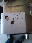
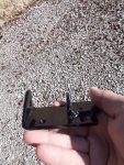
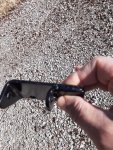
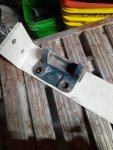
It becomes obvious really quickly that you'll have to make your own new mounting bracket out. I measured up the centerline of the stock belt relative to the stock Kubota mounting bracket. Similar measurements from the 10SI and a little math lead me to determine that the new bracket is .323" closer to the radiator than the stock. I placed the old bracket on top of my stock at this position and transfer punched the mounting holes. I tried to get the mounting point for the new alternator as high as possible. Pay attention to the head of the Hex Head mounting bolt- I ended up positioning the hole so that the edge of the head is held in place by the side of the bracket. The pics kind of show better than I can explain it to you here.
At this point, I removed the alternator drive pulley, spacer and fan. I clocked the alternator to the 6 o'clock position by removing the fasteners that join the body and popping the front case (pulley side) away from the stator (black center section). Rotate the case so that the electrical connectors are pointing downward. Install the fasteners to hold the alternator back together and tighten them up but keep the fan and pully OFF at this point. Try mounting the alternator in the new bracket. Pop the fan on the shaft and make sure it doesn't hit your bracket- don't ask me how I know. I ended up needing to grind the bracket a bit around the mounting hole to avoid interference.
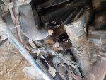
Once I made up the bracket (she ain't pretty and I did weld it in the dark) I realized that there is a splash guard near the crankshaft pulley. This is a piece of sheet metal that interferes with the belt path. I just cut it off To do so, I removed the front left wheel and turned the steering full lock to the left. Reaching in under the radiator hose with a longer sawzall blade made quick work. Be careful not to hit any wiring!
You will need a longer belt. I ended up using a 1/2" x 43" belt. It does work and there is enough room.
Wiring:
Buy the pigtail, I wasn't comfortable with normal sta-con connectors this close to the grounded body of the alternator...
Terminal 1 (White) excite. I spliced this with the white black wire that runs up to the stock voltage regulator - cutting the wire out of each end of the harness. You could run a new wire I suppose, I just used what was there. Under the dash, I unplugged the "CHG" light from the alternator harness. This Terminal 1 wire connects to the CHG light.
Terminal 2 (red) This got a ring terminal and went directly to the alternator output post. I also connected the stock heavy gauge alternator wire to this post. Lastly, I made a jumper from this post to the starter positive lead.
The only other wire you'll need is a ground wire from the alternator to the battery ground on the frame. Please note... My frame ground was pretty bad.. I noticed a really big improvement after I sanded down the metal and used some dielectric (headlight bulb) grease.
I may have missed a detail or two, but this catches the most of it. I'm glad that I did this project- made a big improvement to the tractor and hopefully can help someone else out.
I wanted to replace the dynamo and regulator on my L225 Kubota with D1100 engine and improve charging. Using the readily available 10SI alternator, I was able to do just that! The alternator just fits within the hood assembly and the belt will clear the frame. I wired the excite circuit through the stock charge light on the tach and this does NOT put too much of a strain on the engine at idle. I learned a few things along the way so, I thought that I'd share them to help you out.
What I used:
http://madelectrical.com/electricaltech/delcoremy.shtml (Good reference)
PigTail AutoZone 342372. $4
Alternator Orielly Auto 90-01-3106 $53 + $12 core
Scrap Metal & spray paint
3" Hex head cap screw, nut washer and lock washer
Electrical crimp connectors + 10 GA black wire for alternator ground.
1/2 x 43" belt $11 Rural King
Step1: Disconnect battery
First I removed the stock dynamo and mounting bracket from the engine. I re-positioned the slotted adjustment arm as high as possible to the hood of the tractor. while playing around with position options and "hanging" the alternator from this mounting bracket, I found that IF you place the bracket behind the threaded alternator lug and use about 4 washers between the bracket and alternator, you will have good alignment.
It becomes obvious really quickly that you'll have to make your own new mounting bracket out. I measured up the centerline of the stock belt relative to the stock Kubota mounting bracket. Similar measurements from the 10SI and a little math lead me to determine that the new bracket is .323" closer to the radiator than the stock. I placed the old bracket on top of my stock at this position and transfer punched the mounting holes. I tried to get the mounting point for the new alternator as high as possible. Pay attention to the head of the Hex Head mounting bolt- I ended up positioning the hole so that the edge of the head is held in place by the side of the bracket. The pics kind of show better than I can explain it to you here.
At this point, I removed the alternator drive pulley, spacer and fan. I clocked the alternator to the 6 o'clock position by removing the fasteners that join the body and popping the front case (pulley side) away from the stator (black center section). Rotate the case so that the electrical connectors are pointing downward. Install the fasteners to hold the alternator back together and tighten them up but keep the fan and pully OFF at this point. Try mounting the alternator in the new bracket. Pop the fan on the shaft and make sure it doesn't hit your bracket- don't ask me how I know. I ended up needing to grind the bracket a bit around the mounting hole to avoid interference.
Once I made up the bracket (she ain't pretty and I did weld it in the dark) I realized that there is a splash guard near the crankshaft pulley. This is a piece of sheet metal that interferes with the belt path. I just cut it off
You will need a longer belt. I ended up using a 1/2" x 43" belt. It does work and there is enough room.
Wiring:
Buy the pigtail, I wasn't comfortable with normal sta-con connectors this close to the grounded body of the alternator...
Terminal 1 (White) excite. I spliced this with the white black wire that runs up to the stock voltage regulator - cutting the wire out of each end of the harness. You could run a new wire I suppose, I just used what was there. Under the dash, I unplugged the "CHG" light from the alternator harness. This Terminal 1 wire connects to the CHG light.
Terminal 2 (red) This got a ring terminal and went directly to the alternator output post. I also connected the stock heavy gauge alternator wire to this post. Lastly, I made a jumper from this post to the starter positive lead.
The only other wire you'll need is a ground wire from the alternator to the battery ground on the frame. Please note... My frame ground was pretty bad.. I noticed a really big improvement after I sanded down the metal and used some dielectric (headlight bulb) grease.
I may have missed a detail or two, but this catches the most of it. I'm glad that I did this project- made a big improvement to the tractor and hopefully can help someone else out.
Attachments
-
423.9 KB Views: 220
-
294.4 KB Views: 199
-
936 KB Views: 193
-
987.1 KB Views: 197
-
481.5 KB Views: 230
-
495.3 KB Views: 216
-
326.9 KB Views: 243
-
453.9 KB Views: 195


