I believe I have figured out what you have indicated to me about the connections. I have one question that may be dumb but the PB sleeve looks to be a simple fitting that allows you to connect a hose to the port and run to the tractor port! I have looked online at several different sites for the PB sleeve and they are all from $40 or more with shipping, which just seems unreasonable for such a small fitting. Can you please explain why they are different from a normal fitting to connect the hose? Thanks
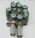
The PB sleeve is specifically made for the valve model. It provides protection to the valve from damage due to high pressure in the valve when you use a valve further downstream. The whole line from pump to valve1 to valve2 becomes a high pressure area. Without the proper sleeve there would be high pressure in parts of the valve that are only designed for low pressure.
You must get the proper PB sleeve for your valve (not just some PB sleeve).
And since you seem not 200% clear on the valve piping and functions of the hoses and ports I will provide some basic information that might help you with the understanding. Ignore it if you do have a good understanding of what the situation is.
The pump will provide flow to the valves on the tractor. Most (probably all really) tractors in today’s world have one valve that controls the three point hitch. So the “standard“ piping would be pump to a hydraulic takeoff block (for future access) then to the three point valve, then dumps to the sump. Most if not all of this piping is internal to the tractor in today’s tractors. All that flow is low pressure until the valve is actuated, then the pressure builds up in the cylinder, line and pump until it does the lift required (or if lift is too much then dumps through the pressure relief valve).
Then there are the additional add on valves like the FEL and rear remote. Those of course require a power in from the pump and must return the oil back to the three point valve. So the power is taken from the hydraulic block mentioned above and diverted to the accessory valve. Then the power must pass through the valve and onto the next valve in line. So the pump becomes connected to the power in (P) of the new valve passes through the valve, into the power beyond sleeve (PB) and to the next valve. The next valve does the same thing and then provides power to the three point valve and dumps into the sump for the pump to then pump around the circuit again and again. This is low pressure until some valve is activated. Most tractors today have a port on the hydraulic block mentioned above that takes the PB flow into the tractor to pipe it to the three point hitch.
Then the new accessory valves have a tank return (T) port. Usually more than one T port is available and often one of these is specifically used for the power beyond sleeve. The others are used to pass the oil returning from the cylinder to the sump. So when a valve is not actuated, the oil flows through but the actuation diverts the oil to one side of the cylinder (I will assume all cylinders are double acting) and that pressure then builds up and moves the piston in the cylinder, lifting the load. That movement of the piston also moves oil out of the cylunder on the non active side. That goes back to the valve and passes through to the T port that then dumps the oil to the sump. That can be through any port on the transmission that is not pressurized. But for simplicity think of it as the fill port for now. But most newer tractors would have this return port on the hydraulic block mentioned above. So T from the valve connects to a low pressure port on the tractor.
The tank return is low pressure and all tank return lines can be connected together into one return line to the tractor. If using the fill port on the transmission you could use a TEE with another TEE or cross above it to have several tank return lines connected together. The tank return is the ONLY hydraulic line that can be teed together with other tank return lines. The power lines must be single continuous flow lines.
The last valve must return power to the tractor three point hitch. If there is a backhoe that must be the last valve before the three point hitch. The backhoe valve is (usually) specifically designed for high pressure and does not use a power beyond sleeve. The tank return line is used as the power beyond on this valve so it is not always a low pressure line and must NOT hook into other T lines!
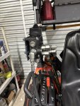
If you look at your L185 you can see most of the pressure piping is external and there may be some obvious block to tap into the pressure line and return pressure to the tractor three point.
Modern and bigger tractors have much of the piping internally to the tractor and you can sometimes just bolt the new valve where there was a cover installed.
 443.5 KB Views: 149
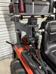 438.6 KB Views: 150
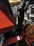 327.8 KB Views: 150
 356 KB Views: 140

.jpg")