Weld-and-Grind, a shop in Edmonton ballparks $2500 to build-up one journal then grind down all the journals.
All-State Ag Parts shows what I need on their site, but a phone call and conversation with Jeff finds that my crank is not in-stock, no core on-hand to refurbish, so a strike-out there.
Dealer is $5k+ for crank and rod and this and that...
So still searching for replacement parts. May take my crank to grinder and tell/pay him to chuck it into his grinder and take that journal down the 0.4mm (16 thou) that is the max undersize journal for which oversize bearing shells are available. There is a CHANCE that grinding down the two increments of undersize on that journal will clean up. In the experience of the crank grinding shop, of the three previous Kubota cranks in his experience, two did not clean up. From my description of "deformations I can catch a fingernail on" he doubts mine will clean up. May pay him to try... what have I got to lose other than a few hundred bucks...
Seller on E-Bay (from china) is ~ $1000 canadian pesos to my door for crank, shells, thrust bearing, gasket set, con-rod, and seal bushings. Seems tempting.
Still checking hither and thither.
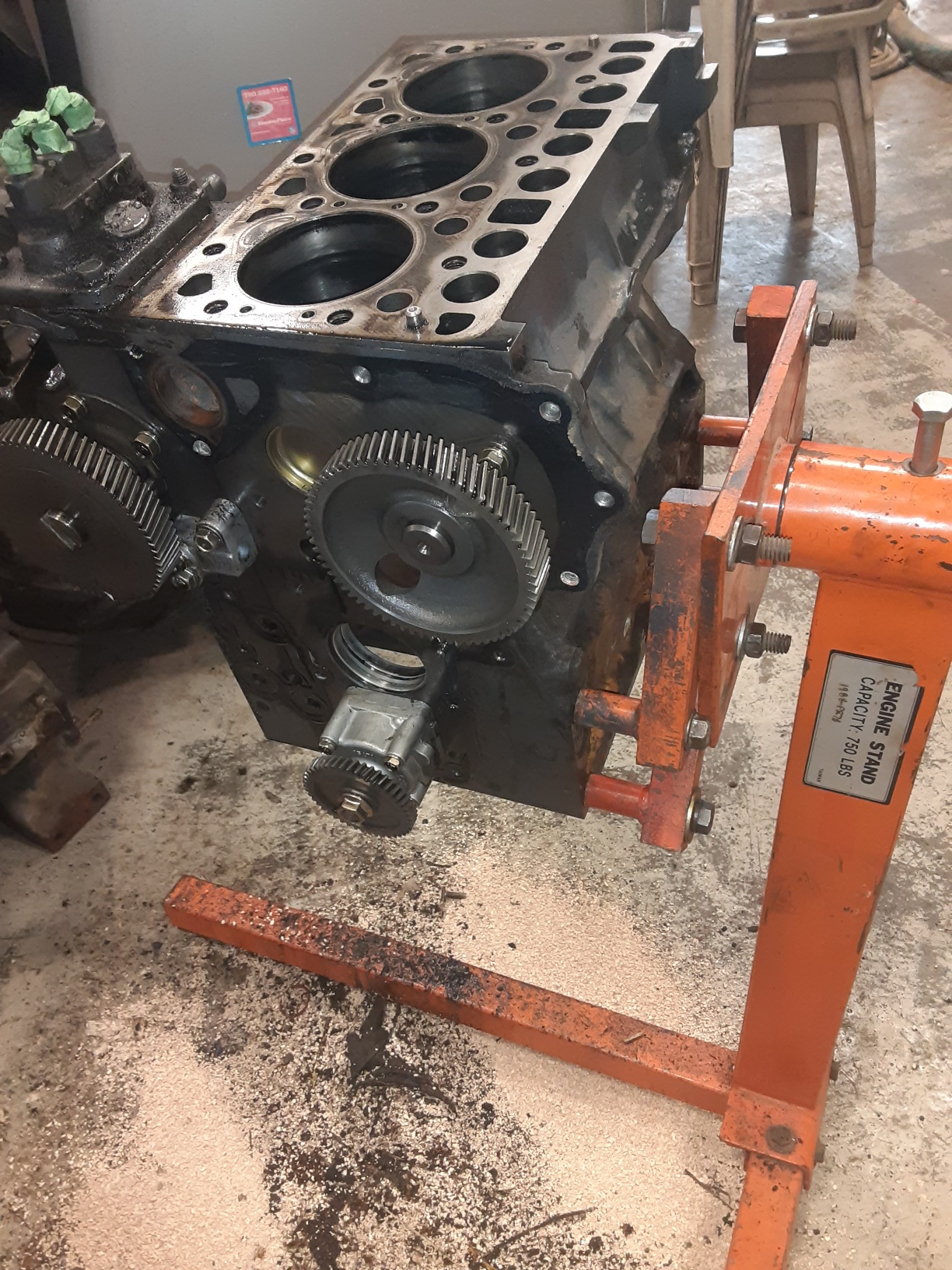
After I hoisted the engine out of frame I mounted the bellhousing end of the engine to an engine work stand. The same way I always do when working an engine. Doesn't work so well on this one. The crankshaft and main bearing carriers load from the flywheel end of the block, and the engine stand mount blocks that access. So I dismounted the engine from stand and manually tipped it over and over to disassemble head and oilpan and crank and stuff. Then I got the brain-wave to mount the engine stand bracket to the SIDE of the engine block, using the frame-mount bolt holes. Mucha betta.
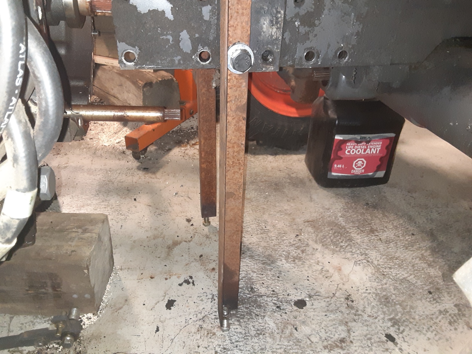
Also a pic of my home-made frame stands that hold the front-half up while splitting. Yes, just rusty scrappy angle iron from the "pile" behind the shop, nothing fancy. Note the "adjustment" bolts on the bottoms that will slide along on the floor. Now that the engine is out, the whole front assembly is unstable and wants to flip over, so theres a similar stand on the nose of the frame to keep whats left of the front half from flipping over.
All-State Ag Parts shows what I need on their site, but a phone call and conversation with Jeff finds that my crank is not in-stock, no core on-hand to refurbish, so a strike-out there.
Dealer is $5k+ for crank and rod and this and that...
So still searching for replacement parts. May take my crank to grinder and tell/pay him to chuck it into his grinder and take that journal down the 0.4mm (16 thou) that is the max undersize journal for which oversize bearing shells are available. There is a CHANCE that grinding down the two increments of undersize on that journal will clean up. In the experience of the crank grinding shop, of the three previous Kubota cranks in his experience, two did not clean up. From my description of "deformations I can catch a fingernail on" he doubts mine will clean up. May pay him to try... what have I got to lose other than a few hundred bucks...
Seller on E-Bay (from china) is ~ $1000 canadian pesos to my door for crank, shells, thrust bearing, gasket set, con-rod, and seal bushings. Seems tempting.
Still checking hither and thither.
After I hoisted the engine out of frame I mounted the bellhousing end of the engine to an engine work stand. The same way I always do when working an engine. Doesn't work so well on this one. The crankshaft and main bearing carriers load from the flywheel end of the block, and the engine stand mount blocks that access. So I dismounted the engine from stand and manually tipped it over and over to disassemble head and oilpan and crank and stuff. Then I got the brain-wave to mount the engine stand bracket to the SIDE of the engine block, using the frame-mount bolt holes. Mucha betta.
Also a pic of my home-made frame stands that hold the front-half up while splitting. Yes, just rusty scrappy angle iron from the "pile" behind the shop, nothing fancy. Note the "adjustment" bolts on the bottoms that will slide along on the floor. Now that the engine is out, the whole front assembly is unstable and wants to flip over, so theres a similar stand on the nose of the frame to keep whats left of the front half from flipping over.

