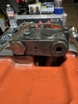
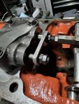
L185DT 3PT Arms Won't Lift

wadeprunty

New member

Equipment
Kubota L185DT, TYM T654 Power Shuttle
May 27, 2024
19
2
3
East Texas
www.facebook.com
Hello, I'm having an issue with my L185DT. The 3PT arms won't lift. I've never had an issue with them before, and they were working just fine a two days ago. I had the tractor off and parked, with a mower lifted in the air. I lowered the mower today and now when I try to lift it nothing happens.

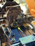
The flow control knob under the the seat, I know it only controls the lowering of the arms, has a 17mm plug/bolt right under it, and I've pulled it and confirmed the fluid is flowing.

I used the fill plug to confirm the hydraulic fluid is at the correct level. All fluids and filters were changed a couple of months ago using OEM parts.

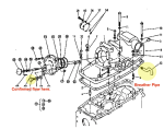
The lift arm lever feels nice and tight, no different than it always has. There is a breather pipe under the seat, if a dirt dauber got in there could that cause this issue? Does anyone know if that breather pipe just threads on and off? I don't want to try to turn it without confirming that first.

Also, my tractor has never had a front loader, so no extra hose runs to work through.

With this information, can anyone point me to some other things to look at? Maybe a process of elimination to work through? I'm fairly new to all of this, but I learn quickly...I've already rebuilt the front right axle.

Thanks!
IMG_0482.jpeg Screenshot 2024-07-24 at 5.49.14 PM.png
 
Last edited:

Russell King

Well-known member
Lifetime Member

Equipment
L185F, Modern Ag Competitor 4’ shredder, Rhino tiller, rear dirt scoop
Jun 17, 2012
5,371
1,418
113
Austin, Texas
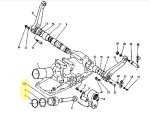
There is a feedback rod that connects the small lift arms to the valve inside the tractor case. See item 39 in this picture and make sure it is connected at both ends and isn’t very loose at either end.

IMG_0130.png

You can try to remove any load from the arms and see if the arms will raise. That would indicate that the piston seal is leaking and can’t build up pressure to create force to lift.

You can also lift the arm slightly to make sure they can move up at all. Don’t move the arms up much since there is a loose connection between some internal parts that can cause parts to fall out of position under the condition of now down force on the arms.
 

wadeprunty

New member

Equipment
Kubota L185DT, TYM T654 Power Shuttle
May 27, 2024
19
2
3
East Texas
www.facebook.com
There is a feedback rod that connects the small lift arms to the valve inside the tractor case. See item 39 in this picture and make sure it is connected at both ends and isn’t very loose at either end.

View attachment 133421
You can try to remove any load from the arms and see if the arms will raise. That would indicate that the piston seal is leaking and can’t build up pressure to create force to lift.

You can also lift the arm slightly to make sure they can move up at all. Don’t move the arms up much since there is a loose connection between some internal parts that can cause parts to fall out of position under the condition of now down force on the arms.
Ding ding ding! With no load the arms raise just fine. As soon as I step on them though they don’t move at all. Researching the piston seal now. Thank you so much!
 

wadeprunty

New member

Equipment
Kubota L185DT, TYM T654 Power Shuttle
May 27, 2024
19
2
3
East Texas
www.facebook.com
There is a feedback rod that connects the small lift arms to the valve inside the tractor case. See item 39 in this picture and make sure it is connected at both ends and isn’t very loose at either end.

View attachment 133421
You can try to remove any load from the arms and see if the arms will raise. That would indicate that the piston seal is leaking and can’t build up pressure to create force to lift.

You can also lift the arm slightly to make sure they can move up at all. Don’t move the arms up much since there is a loose connection between some internal parts that can cause parts to fall out of position under the condition of now down force on the arms.
Would this be the piston you‘re referring to, and would the o-ring and back-up ring be what needs to be replaced?
IMG_0242.jpeg IMG_0243.jpeg
 

Russell King

Well-known member
Lifetime Member

Equipment
L185F, Modern Ag Competitor 4’ shredder, Rhino tiller, rear dirt scoop
Jun 17, 2012
5,371
1,418
113
Austin, Texas
Would this be the piston you‘re referring to, and would the o-ring and back-up ring be what needs to be replaced?
View attachment 133440 View attachment 133441
Yes and yes.

There may be other problems in that system but I would thing you will see any problems when you get into it. The cylinder wall may be pitted, the piston may have some problems…

I have never dealt with that area before and there is a pressure relief valve in there and I think the plug you removed is a port that can be used to check pressure. So the other thing to check is the pump is able to create pressure but I would not think that would be a problem just sitting there for a few days.

I believe there is a good diagram in the operating manual or the work shop manual that shows how it works.

Good luck!
 

wadeprunty

New member

Equipment
Kubota L185DT, TYM T654 Power Shuttle
May 27, 2024
19
2
3
East Texas
www.facebook.com
Yes and yes.

There may be other problems in that system but I would thing you will see any problems when you get into it. The cylinder wall may be pitted, the piston may have some problems…

I have never dealt with that area before and there is a pressure relief valve in there and I think the plug you removed is a port that can be used to check pressure. So the other thing to check is the pump is able to create pressure but I would not think that would be a problem just sitting there for a few days.

I believe there is a good diagram in the operating manual or the work shop manual that shows how it works.

Good luck!
Awesome. Thank you so much for the help, and all the information! I’ll report back once I’ve gotten into it and let you know how things go.
 

wadeprunty

New member

Equipment
Kubota L185DT, TYM T654 Power Shuttle
May 27, 2024
19
2
3
East Texas
www.facebook.com
Yes and yes.

There may be other problems in that system but I would thing you will see any problems when you get into it. The cylinder wall may be pitted, the piston may have some problems…

I have never dealt with that area before and there is a pressure relief valve in there and I think the plug you removed is a port that can be used to check pressure. So the other thing to check is the pump is able to create pressure but I would not think that would be a problem just sitting there for a few days.

I believe there is a good diagram in the operating manual or the work shop manual that shows how it works.

Good luck!
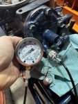
OK, so here’s where I’m at. I replaced the o-rings on the 3pt arm piston and the housing cover right in front of it. This did not fix the issue, so I got me a hydraulic gauge and I’m not seeing anything show up on it. Fluid will flow through it, but there’s not enough pressure to make the needle move. From there I pulled the hydraulic pump and rebuilt it. Still nothing. I don’t really know where to go from here. I’ve also replaced the hydraulic filter and fluids.

The arms will go up with no weight, and the throttle up. No throttle, or add weight and they won’t budge. What should I look at next? I’m not frustrated, I actually like tearing this apart and learning how all of this works. Thanks for your help!

IMG_0603.jpeg
 

TheOldHokie

Well-known member
Lifetime Member

Equipment
L3901/LA525, B7200DT/B1630, G2160/RCK60, G2460/RCK60
Apr 6, 2021
8,775
4,510
113
Myersville, MD
windyridgefarm.us
OK, so here’s where I’m at. I replaced the o-rings on the 3pt arm piston and the housing cover right in front of it. This did not fix the issue, so I got me a hydraulic gauge and I’m not seeing anything show up on it. Fluid will flow through it, but there’s not enough pressure to make the needle move. From there I pulled the hydraulic pump and rebuilt it. Still nothing. I don’t really know where to go from here. I’ve also replaced the hydraulic filter and fluids.

The arms will go up with no weight, and the throttle up. No throttle, or add weight and they won’t budge. What should I look at next? I’m not frustrated, I actually like tearing this apart and learning how all of this works. Thanks for your help!

View attachment 134814
Looks like your gauge is hooked up to the lift cylinder. If it had pressure it would be working so thats not a surprising result.

You need to move your test point closer to the pump to verify it is working. Resist the urge to "tear things apart" and focus on understanding and analyzing the hydraulic circuit.

Dan
 
Last edited:

wadeprunty

New member

Equipment
Kubota L185DT, TYM T654 Power Shuttle
May 27, 2024
19
2
3
East Texas
www.facebook.com
Looks like your gauge is hooked up to the lift cylinder. If it had pressure it would be working so thats not a surprising result.

You need to move your test point closer to the pump to verify it is working. Resist the urge to "tear things apart" and focus on understanding and analyzing the hydraulic circuit.

Dan
I know of no other point to make a connection to the circuit. Here are the two options given by the shop manual. One is the port I used, and the other is disconnecting the discharge pipe from the pump and making a relief valve/pressure gauge connection at the pump outlet, but I cannot find any adapter or couplet that would make this possible. I understand what to do here, and how it works, but I'm not a machinist (yet), so I don't have a way to make that connection. If the manual says to do it this way it makes me think that technicians at some point would have had something like this, but I cannot find it. I am all ears if you know of a way to do this.

Per the shop manual:

116. PUMP DISCHARGE PRESSURE
To isolate pump from hydraulic system and check pump discharge pressure, proceed as follows: Disconnect discharge pipe from pump and install a pressure gage and flow control valve as shown in Fig. 153. Place pressure gage return hose into reservoir filler opening.

With hydraulic fluid a t operating temperature and engine operating at high idle speed, slowly close flow control valve until specified pump pressure of 13240-14690 kPa (1920-2130 psi) is ob- tained. If specified pump pressure can- not be obtained, remove and overhaul or renew pump.


117. SYSTEM PRESSURE
Hydraulic system relief pressure should be 13240-14690 kPa (1920-2130 psi) on all models. To check relief pressure, remove plug from test port in hydraulic cylinder cover and install a pressure gage

IMG_0586.jpeg
 

TheOldHokie

Well-known member
Lifetime Member

Equipment
L3901/LA525, B7200DT/B1630, G2160/RCK60, G2460/RCK60
Apr 6, 2021
8,775
4,510
113
Myersville, MD
windyridgefarm.us
I know of no other point to make a connection to the circuit. Here are the two options given by the shop manual. One is the port I used, and the other is disconnecting the discharge pipe from the pump and making a relief valve/pressure gauge connection at the pump outlet, but I cannot find any adapter or couplet that would make this possible. I understand what to do here, and how it works, but I'm not a machinist (yet), so I don't have a way to make that connection. If the manual says to do it this way it makes me think that technicians at some point would have had something like this, but I cannot find it. I am all ears if you know of a way to do this.

Per the shop manual:

116. PUMP DISCHARGE PRESSURE
To isolate pump from hydraulic system and check pump discharge pressure, proceed as follows: Disconnect discharge pipe from pump and install a pressure gage and flow control valve as shown in Fig. 153. Place pressure gage return hose into reservoir filler opening.

With hydraulic fluid a t operating temperature and engine operating at high idle speed, slowly close flow control valve until specified pump pressure of 13240-14690 kPa (1920-2130 psi) is ob- tained. If specified pump pressure can- not be obtained, remove and overhaul or renew pump.


117. SYSTEM PRESSURE
Hydraulic system relief pressure should be 13240-14690 kPa (1920-2130 psi) on all models. To check relief pressure, remove plug from test port in hydraulic cylinder cover and install a pressure gage

View attachment 134854
I am quite familiar with the WSM procedures. I can probably come up with what yoy need but it might tale me a few days. PM me if you would like some help.

Dan
 
Last edited:

Russell King

Well-known member
Lifetime Member

Equipment
L185F, Modern Ag Competitor 4’ shredder, Rhino tiller, rear dirt scoop
Jun 17, 2012
5,371
1,418
113
Austin, Texas
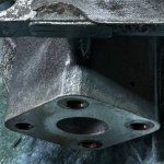
The hydraulic pump has the inlet pipe on bottom and the outlet on top. They have four bolts holding them to the pump. There is an oring between the pipe and the pump to seal them together.

From looking at the bad picture in the manual and the text you will need get a plate machined with the bolt pattern to attach to the top of the pump (outlet) that has a tapped hole in it. Then you will basically put a tee into that hole with your gauge installed on one of the outlets and a needle valve on the other outlet. Then from the valve a hose will go into the transmission fill opening. Getting the flow control valve to low flow will raise the pressure in the valve. That way your pump is not deadheaded if the valve is NOT 100% closed (so always know the valve is open before you start the tractor). They may make a valve that can not be 100% closed but I don’t know for certain.

There may be a block in the piping that crosses over the top of the transmission that has a cover on it. If so that could be used instead. I got a cover from @TheOldHokie that replaces the cover and allows for the attachment of accessory hydraulics. See this thread for some good information on the block. @torch was also making the blocks but I think he is in Canada. You could get a cover made locally with the dimensions in the thread.

Whatever you do just DO NOT deadhead the pump during the test or when you put it back together! The only pressure relief valve is inside the three point system so the pump is not protected in this testing.

@TheOldHokie will be able to give you better advice but I just wanted to give you the general idea.

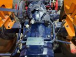
I think you have posted pictures of your tractor but don’t remember if you have any accessories in the hydraulic system but to help you should take the same picture you posted ab without the blue rag covering that area (if there is a block there). If you have anything connected to the hydraulic system post a picture of that so that it can be evaluated for possible tapping into locations.

One last question - were there any Teflon backer rings involved with the oring on the cylinder? Did you replace them?

Good luck.
 
  • Like
Reactions: 1 users

ruger1980

Active member

Equipment
L4310 w/La682, L225
Oct 25, 2020
396
145
43
CNY
Look for a pipe plug in one or the other ends of the plate circled in orange below. There should be a drilling to port the 2 openings on the plate together. You can tap a gauge into this area and determine what if any pressure can be read before the valve. The gauge you have may be too large to show any pressure without an activation and a load to provide resistance. If there is a plug it is probably BSP
As an alternative you could drill and tap at the spot marked X but using the plate would be much easier. If need be you can always drill the plate and tap for an 1/8npt plug/fitting.

1723656860058.png
1723656924841.png
 

wadeprunty

New member

Equipment
Kubota L185DT, TYM T654 Power Shuttle
May 27, 2024
19
2
3
East Texas
www.facebook.com
The hydraulic pump has the inlet pipe on bottom and the outlet on top. They have four bolts holding them to the pump. There is an oring between the pipe and the pump to seal them together.

From looking at the bad picture in the manual and the text you will need get a plate machined with the bolt pattern to attach to the top of the pump (outlet) that has a tapped hole in it. Then you will basically put a tee into that hole with your gauge installed on one of the outlets and a needle valve on the other outlet. Then from the valve a hose will go into the transmission fill opening. Getting the flow control valve to low flow will raise the pressure in the valve. That way your pump is not deadheaded if the valve is NOT 100% closed (so always know the valve is open before you start the tractor). They may make a valve that can not be 100% closed but I don’t know for certain.

There may be a block in the piping that crosses over the top of the transmission that has a cover on it. If so that could be used instead. I got a cover from @TheOldHokie that replaces the cover and allows for the attachment of accessory hydraulics. See this thread for some good information on the block. @torch was also making the blocks but I think he is in Canada. You could get a cover made locally with the dimensions in the thread.

Whatever you do just DO NOT deadhead the pump during the test or when you put it back together! The only pressure relief valve is inside the three point system so the pump is not protected in this testing.

@TheOldHokie will be able to give you better advice but I just wanted to give you the general idea.

I think you have posted pictures of your tractor but don’t remember if you have any accessories in the hydraulic system but to help you should take the same picture you posted ab without the blue rag covering that area (if there is a block there). If you have anything connected to the hydraulic system post a picture of that so that it can be evaluated for possible tapping into locations.

One last question - were there any Teflon backer rings involved with the oring on the cylinder? Did you replace them?

Good luck.
First thing. IT WORKS! I'll get to that in just a second.

Yes, I understand not wanting to deadhead it. The shop manual you provided me a while back does explain that you need to have a control valve that you can slowly close (not fully) as you watch the pressure raise. I'd like to have a plate machined at that block to run a valve off of for a rear remote. If I do that I'll also have a port drilled and threaded there for pressure testing. That's a great idea.

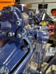
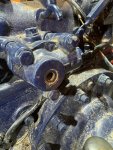
OK, so as I've been going through and familiarizing myself with the exploded diagrams in K-Pad this tractor looks like it's been Frankensteined together. The guy that sold it to me gave me this story of how this specific tractor was owned by a single family who took really good care of it, and it was garage kept its entire life. Well, outside of the fenders looking like a 4 year old with a hammer played on them, and the rust and non-period correct blue spray paint on everything, I've been finding all kinds of wrong pieces and parts in places, which I have been replacing as I go. And, I know that guy buys these in any shaped and makes a running tractor out of a bunch of them. One of these Mary Shelley areas is the hydraulic system. I'm sure this is a replacement pump, and the relief valve does not match what's in the manual, or any L185 photos I've seen. There's a complete pressure block assembly missing, and the relief valve looks like one off maybe an L275. I'll add photos

So, I just decided to replace all the o-rings on the pump, the relief valve, the spacer valve and that accessory block. And, that's after replacing the piston and 3pt descent valve cover o-rings. So, pretty much every o-ring and that backer ring on the piston. None of the o-rings were damaged or missing, but they were all pretty hard.

At first I didn't get anything, it still responded just the same, but I kept the RPMs up and raised the arms, and kept pushing on them with my foot as I raised it. I noticed as it got higher, there would be a little force to it. I did this over and over and the force kept getting stronger the lower the arms got, until finally the force started from the very bottom, and it could fully lift me (240lbs) in the air like I was a sack of potatoes. I connected the flail mower back up, and it lifted it with no issue, even with the throttle at idle. So, I guess once I resolved the overall issue, I then needed to remove the air in the system.

I'm not sure if there were different versions of the L185DT sent out, with different hydraulic setups, but I'm putting everything back on this like it is in the manual. This is the first tractor I've owed that I'm learning how to fix things myself, so I'm happy to do it. I just ordered that pressure block assembly, and I have all the correct bolts, studs and washers for it coming from my local dealer. The pressure relive valve currently on it just has an extra hex bold drilled through the center, but the internals seem to be the same as one without that, so I might leave it alone. I did check that port too with the pressure gauge, but nothing registered there either.

Thanks for all the advice with this. I'm sure as I continue one with it I'll be back with more questions.

IMG_0615.jpeg IMG_0610.jpeg IMG_0607.jpeg IMG_0583.jpeg
 

TheOldHokie

Well-known member
Lifetime Member

Equipment
L3901/LA525, B7200DT/B1630, G2160/RCK60, G2460/RCK60
Apr 6, 2021
8,775
4,510
113
Myersville, MD
windyridgefarm.us
First thing. IT WORKS! I'll get to that in just a second.

Yes, I understand not wanting to deadhead it. The shop manual you provided me a while back does explain that you need to have a control valve that you can slowly close (not fully) as you watch the pressure raise. I'd like to have a plate machined at that block to run a valve off of for a rear remote. If I do that I'll also have a port drilled and threaded there for pressure testing. That's a great idea.

OK, so as I've been going through and familiarizing myself with the exploded diagrams in K-Pad this tractor looks like it's been Frankensteined together. The guy that sold it to me gave me this story of how this specific tractor was owned by a single family who took really good care of it, and it was garage kept its entire life. Well, outside of the fenders looking like a 4 year old with a hammer played on them, and the rust and non-period correct blue spray paint on everything, I've been finding all kinds of wrong pieces and parts in places, which I have been replacing as I go. And, I know that guy buys these in any shaped and makes a running tractor out of a bunch of them. One of these Mary Shelley areas is the hydraulic system. I'm sure this is a replacement pump, and the relief valve does not match what's in the manual, or any L185 photos I've seen. There's a complete pressure block assembly missing, and the relief valve looks like one off maybe an L275. I'll add photos

So, I just decided to replace all the o-rings on the pump, the relief valve, the spacer valve and that accessory block. And, that's after replacing the piston and 3pt descent valve cover o-rings. So, pretty much every o-ring and that backer ring on the piston. None of the o-rings were damaged or missing, but they were all pretty hard.

At first I didn't get anything, it still responded just the same, but I kept the RPMs up and raised the arms, and kept pushing on them with my foot as I raised it. I noticed as it got higher, there would be a little force to it. I did this over and over and the force kept getting stronger the lower the arms got, until finally the force started from the very bottom, and it could fully lift me (240lbs) in the air like I was a sack of potatoes. I connected the flail mower back up, and it lifted it with no issue, even with the throttle at idle. So, I guess once I resolved the overall issue, I then needed to remove the air in the system.

I'm not sure if there were different versions of the L185DT sent out, with different hydraulic setups, but I'm putting everything back on this like it is in the manual. This is the first tractor I've owed that I'm learning how to fix things myself, so I'm happy to do it. I just ordered that pressure block assembly, and I have all the correct bolts, studs and washers for it coming from my local dealer. The pressure relive valve currently on it just has an extra hex bold drilled through the center, but the internals seem to be the same as one without that, so I might leave it alone. I did check that port too with the pressure gauge, but nothing registered there either.

Thanks for all the advice with this. I'm sure as I continue one with it I'll be back with more questions.

View attachment 134977 View attachment 134978 View attachment 134979 View attachment 134980
First question - are you getting factory specified pressiure at the gauge?

The rectangular block in ypur picture can be replaced with one that has two ports in it for hooking up external hydraulics. It can also be used to directly test the pump discharge pressure using the gauge and throttle valve setup described in the manual.

Dan
 

Russell King

Well-known member
Lifetime Member

Equipment
L185F, Modern Ag Competitor 4’ shredder, Rhino tiller, rear dirt scoop
Jun 17, 2012
5,371
1,418
113
Austin, Texas
I am glad you got it going but what you did should not have fixed anything that had been moving before. But who am I to argue about success.

Have you drained the transmission fluid and replaced the filter screen that is the inlet to the pump? If not, I would put that high on your list of things to do.

I will compare your pictures to my L185. I didn’t see anything that jumped out as odd but don’t look at it that closely now to remember exactly what it looks like.

The block on top of the transmission looks identical to what I remember mine was. But Kubota had that identical arrangement on several different models.

Since you have the gauge and fittings would you hook it back to that port and measure the pressure as you raise the three point hitch? Then report the pressure back please as TheOldHokie asked.
 
  • Like
Reactions: 1 user

wadeprunty

New member

Equipment
Kubota L185DT, TYM T654 Power Shuttle
May 27, 2024
19
2
3
East Texas
www.facebook.com
I am glad you got it going but what you did should not have fixed anything that had been moving before. But who am I to argue about success.

Have you drained the transmission fluid and replaced the filter screen that is the inlet to the pump? If not, I would put that high on your list of things to do.

I will compare your pictures to my L185. I didn’t see anything that jumped out as odd but don’t look at it that closely now to remember exactly what it looks like.

The block on top of the transmission looks identical to what I remember mine was. But Kubota had that identical arrangement on several different models.

Since you have the gauge and fittings would you hook it back to that port and measure the pressure as you raise the three point hitch? Then report the pressure back please as TheOldHokie asked.
OK, so I'm back with more info, and she's not working again, and this started again almost immediately. I apologize for taking weeks to get back to this, but we have a newborn, and so life is totally chaotic at the moment.

When the arms began working I connected the flail mower to her and took a single pass with just to see if they would remain working. Immediately after the arms would not lift. I put the gauge on and I'm not seeing any pressure at all. Again, just like before, the arms will lift with no weight connected and the throttle up. If there is any weight, or the throttle is completely down, the arms will not raise.

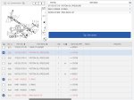
The combination of the exploded diagram in K-Pad, and what my tractor actually has installed on it really had me confused, until I got to look at the bolts for the oil pressure block. Let me explain. My tractor does not have an oil pressure block. On this block is where people were telling me to connect my gauge, and I thought because it wasn't there, and K-Pad showed it being there, that it was missing from mine. So I was going to purchase one, but went to my local dealership to make sure I could get all the other parts, like bolts and studs, to connect it all up. K-Pad shows different bolts for different serial numbers, and once I got to look at one from each is when I realized that the earlier models didn't have the oil pressure block. The bolts for those are shorter by the exact width of the oil pressure block. The relief valve is also a little different on my tractor verses what is shown in the main image in K-Pad, but it does show the one I have as an alternative relief valve. My relieve valve actually has a a plug on the end of it that you should be able to connect to with a gauge. I've tried connecting here and still do not get any reading on the gauge. I actually changed gauges, just to make sure that wasn't giving false readings, but no gauge I've tried gives me a pressure reading.

So, I have removed the wire mesh filter, which is a new OEM filter, and confirmed that it isn't plugged. I blew out both inlet and outlet hydraulic lines that go to the pump, and found no blockage there. I've replaced all o-rings on the inlet and outlet lines, the block that sits in front of the cylinder housing, the piston, and the cylinder assembly cover. I'm also making sure to fill with fluid until it runs out of the fill level port on the side of the tank.

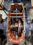
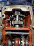
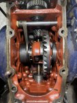
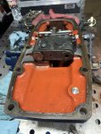
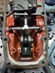
Once this was done, and it still wasn't working, I drained my fluid, and took the entire cylinder cover off. Everything inside looks great. All the gears look almost brand new, and there was no corrosion anywhere. There was a very small amount of silver sludge at the bottom in the back corner, but I cleaned that out. Since it was now accessible, I replaced all the o-rings in the control valve. I put it all back together, with the gasket being the only expense of this process, about $30, but it is still acting the exact same.

Since I wasn't getting any pressure at the port on the relief valve, I went ahead and changed out the pump. I know, I know, I threw parts at it, but in my mind I'm following the process of elimination. I have a sealed system. There are no leaks anywhere. I'm not loosing fluid. There is no external sign of fluid penetrating any other area that has an o-ring, so I don't think pressure is escaping. My only conclusion is that internally pressure is escaping from the pressurized side to the un-pressurized side, but I cannot figure out where that would be.

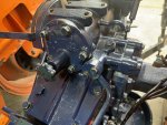
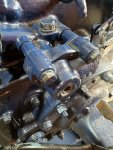
I'll leave some photos I've taken now that I've had it opened. Maybe you can see something here that I don't know to look for.

Thanks again for everyone's help and suggestions.

IMG_0737.jpeg IMG_0736.jpeg IMG_0671.jpeg IMG_0673.jpeg IMG_0674.jpeg IMG_0675.jpeg IMG_0676.jpeg IMG_0678.jpeg IMG_0679.jpeg