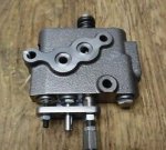
L1801 hydraulics problem.

TheOldHokie

Well-known member
Lifetime Member

Equipment
L3901/LA525, B7200DT/B1630, G2160/RCK60, G2460/RCK60
Apr 6, 2021
8,928
4,668
113
Myersville, MD
windyridgefarm.us
You're right. Your tractor is missing a whole section of gearbox that is visible in the other pic (probably another gear splitter hi/lo type of thing) and your 3pt pressure feed line has no hydraulic 'block' there.

The good news is i don't think your loader valve NEEDS a separate 'power beyond' port to be put in series with your 3pt, because it is a 'sectional' valve for which power beyond would probably split off at the 'outlet' housing, meaning all the passages of everything in between were designed to withstand high pressure. In fact, it seems likely your inlet and outlet sections on that valve are identical other than having their ports drilled in from opposite ends. So that entire valve assembly can handle high pressure. Therefore you can just power your 3pt from the outlet of your loader valve, and while using the 3pt your loader valve will have pressure on both its inlets and outlets and will not work until you release the 3pt handle, but it won't blow up either. The issue with that approach is that you would still need the pressure relief valve between the pump and loader valve since the loader valve does not have its own pressure relief.

It does seem odd to me as well that you have a dual-acting valve with only one work port connected to anything and the other blocked, but this may make sense if your loader lift cylinders are single acting and do not have 'power down', or in other words only drop by gravity. A picture of the entire loader would help. Regarding the comment about 'deadheading' with that blocked port, im assuming the long screw coming out of the bottom of that valve section is and adjustable stopper that (if set correctly) would prevent you from moving the spool to the position that would deadhead the pump against the blocked port.

If you are willing to do compression fittings on your pressure feed line, you could install fittings into the pressure line in the same area that the hydraulic block exists on the other tractor, and your existing hoses may even reach there and not need to be swapped out for different hoses. You could potentially even package the pressure relief valve into this area somehow. Replacing the loader valve with one with an internal pressure relief is still an option.

If you are not willing to do compression fittings on your pressure feed line, then a 'fitting block' between the pump outlet and the pressure line would probably be the next easiest.
Thats some poor advice. Sectionsl valves are no different than monoblock and require a power beyond mechanism that isolates the neutral core from the tank core when being used for high pressure carryover. This is not a structural strength issue. There are a multitude of issues but two that leap to mind:
  1. The seals on the ends of the spools see tank core pressure and are not designed to handle much more than 500 PSI. Start subjecting them to 2000+ PSI neutral core pressure and you are begging for seal failures and leaks.
  2. Any inlet or port relief valves unload to tank. If tank pressure is the same as neutral port pressure they cannot do their job.
Number 2 is not an issue with his valve but number 1 definitly is.

Dan
 

North Idaho Wolfman

Moderator
Staff member
Lifetime Member

Equipment
L3450DT-GST, Woods FEL, B7100 HSD, FEL, 60" SB, 743 Bobcat with V2203, and more
Jun 9, 2013
30,552
6,599
113
Sandpoint, ID
There WAS a adapter block that WAS available that fits under this plate to give you remote hydraulics, but that adapter is long gone.
So cutting the line and making a loop is the easiest.

1681839182320.png
 
  • Like
Reactions: 1 user

North Idaho Wolfman

Moderator
Staff member
Lifetime Member

Equipment
L3450DT-GST, Woods FEL, B7100 HSD, FEL, 60" SB, 743 Bobcat with V2203, and more
Jun 9, 2013
30,552
6,599
113
Sandpoint, ID
The two lines for the loader are this:
Tank being an un obstructive return, the power line is off an auxiliary port on the three point control.
Hence why you have to have the three point in active lift position for it to work.


1681839477745.png
 

TheOldHokie

Well-known member
Lifetime Member

Equipment
L3901/LA525, B7200DT/B1630, G2160/RCK60, G2460/RCK60
Apr 6, 2021
8,928
4,668
113
Myersville, MD
windyridgefarm.us
There WAS a adapter block that WAS available that fits under this plate to give you remote hydraulics, but that adapter is long gone.
So cutting the line and making a loop is the easiest.

View attachment 100592
Thats why I asked for a look at the underside. If there was a factory provision for an adapter making one should be pretty damn easy. Basically just drill a few 8mm holes in a small block of aluminum.

Dan
 

TheOldHokie

Well-known member
Lifetime Member

Equipment
L3901/LA525, B7200DT/B1630, G2160/RCK60, G2460/RCK60
Apr 6, 2021
8,928
4,668
113
Myersville, MD
windyridgefarm.us
The two lines for the loader are this:
Tank being an un obstructive return, the power line is off an auxiliary port on the three point control.
Hence why you have to have the three point in active lift position for it to work.


View attachment 100593
I will also add it would be gross engineering malpractice if there were no system pressure relief in that 3pt circuit.

Dan
 

Vigo

Well-known member

Equipment
B6100, B8200
Jan 9, 2022
595
340
63
San Antonio Texas
Thats some poor advice. Sectionsl valves are no different than monoblock and require a power beyond mechanism that isolates the neutral core from the tank core when being used for high pressure carryover. This is not a structural strength issue. There are a multitude of issues but two that leap to mind:
  1. The seals on the ends of the spools see tank core pressure and are not designed to handle much more than 500 PSI. Start subjecting them to 2000+ PSI neutral core pressure and you are begging for seal failures and leaks.
  2. Any inlet or port relief valves unload to tank. If tank pressure is the same as neutral port pressure they cannot do their job.
Number 2 is not an issue with his valve but number 1 definitly is.

Dan
1 is a fair point, which begs the question of what is the difference between a simple o-ring or lip seal in a cylinder piston or gland vs on a spool valve? Perhaps a safer statement would be if a sectional valve had the possibility of PB at all, that passage exists already in the valve sections and could be accessed if one modified the end housing to access it. But both are probably further down the rabbit hole than OP is trying to go so rather than be entirely off-topic, it'd be better for me to toe the line and retract my statement about the whole idea. :)

I think i just enjoy the 'mad max' scenario of make this work in a post-apocalyptic landscape where you can't order anything from anyone, but it would certainly be better to just follow the normal paths (hydraulic block to go under some flange in the pressure line and/or loader valve with internal relief) in this case rather than 'mcguyver-ing' it too much.
 
Last edited:

North Idaho Wolfman

Moderator
Staff member
Lifetime Member

Equipment
L3450DT-GST, Woods FEL, B7100 HSD, FEL, 60" SB, 743 Bobcat with V2203, and more
Jun 9, 2013
30,552
6,599
113
Sandpoint, ID
I will also add it would be gross engineering malpractice if there were no system pressure relief in that 3pt circuit.

Dan
The three point and pressure relief valve are normally are located in the cover of the three point cylinder.
 

TheOldHokie

Well-known member
Lifetime Member

Equipment
L3901/LA525, B7200DT/B1630, G2160/RCK60, G2460/RCK60
Apr 6, 2021
8,928
4,668
113
Myersville, MD
windyridgefarm.us
1 is a fair point, which begs the question of what is the difference between a simple o-ring or lip seal in a cylinder piston or gland vs on a spool valve? Perhaps a safer statement would be if a sectional valve had the possibility of PB at all, that passage exists already in the valve sections and could be accessed if one modified the end housing to access it. But both are probably further down the rabbit hole than OP is trying to go so rather than be entirely off-topic, it'd be better for me to toe the line and retract my statement about the whole idea. :)

I think i just enjoy the 'mad max' scenario of make this work in a post-apocalyptic landscape where you can't order anything from anyone, but it would certainly be better to just follow the normal paths in this case rather tha 'mcguyver-ing' it too much.
Power beyond is simply an isolation device installed at the junction of the neutral core and dual tank cores. That junction is located at the outlet end of the tank (2) and neutral (1) cores.

Without the device all three cores are connected. With the device installed the two tank cores are connected and isolated from the neutral core leaving you with two independent outlet paths.

The same is true for a closed center conversion device which also plugs the neutral core exit port leaving you with just a tank exit path.

Seals are designed for the intended service. The spool seals are designed with the expectation that they will never see elevated pressures. Could they be designed as high pressure seals? Sure but they arent.

Dan
 

Vigo

Well-known member

Equipment
B6100, B8200
Jan 9, 2022
595
340
63
San Antonio Texas
Power beyond is simply an isolation device installed at the junction of the neutral core and dual tank cores. That junction is located at the outlet end of the tank (2) and neutral (1) cores.
Since the end of a sectional valve surface is a flat flange with some holes in it, i believe you would just be intercepting the neutral 'hole' before it 'dumped' into the common area in the outlet manifold. I was just suggesting that modifying the outlet housing to create a PB port would be a lot easier on a sectional valve than modifying a monoblock valve with a totally undrilled PB port. Still beyond the scope of most DIY ambitions, and thus of limited relevance to anyone...

If the pressure port that is in use with this loader Tees or parallels off the 3pt cylinder, it would only be able to operate the loader while the 3pt valve was in the 'raise' position, so the 3pt relief valve would be protecting the loader. That correlates to what was described in the original 2019 post. If there were no relief hooked to the circuit it would have broken itself within seconds of pulling the first loader handle. Thus my confusion about the 2023 post wanting to add a relief valve when it clearly has one or it would have broken itself in the first use.

I feel bad about going so far down rabbit holes when i still think the original desire to add an external relief was based on a misunderstanding. The 3pt relief has been protecting the loader circuit this entire time. The only reason to add a separate relief is if the OP wishes to 'divorce' the loader from the 3pt plumbing, which may address the original symptom from 2019, but is not listed as part of any motivation in the 2023 posts.
 

TheOldHokie

Well-known member
Lifetime Member

Equipment
L3901/LA525, B7200DT/B1630, G2160/RCK60, G2460/RCK60
Apr 6, 2021
8,928
4,668
113
Myersville, MD
windyridgefarm.us
Since the end of a sectional valve surface is a flat flange with some holes in it, i believe you would just be intercepting the neutral 'hole' before it 'dumped' into the common area in the outlet manifold. I was just suggesting that modifying the outlet housing to create a PB port would be a lot easier on a sectional valve than modifying a monoblock valve with a totally undrilled PB port. Still beyond the scope of most DIY ambitions, and thus of limited relevance to anyone...
Modifying the outlet on a sectional valve is just as hard as a monoblock. Here is why. In a sectional the end cover will look like this. T1, T2, and T are all connected to N. The carry over sleeve is the isolation device and you can see it is more than just a plug.

OpenCenter.jpg


When the carry over sleeve is installed it seals the center port of the outlet block off from the T1 and T2 cavities. The cavity needed for installing the HPCO sleeve is non-trivial to make and certainly a major push for my DIY skills.

With_HPCO.jpg


What you can do however is make a new outlet block that cuts off the N core and passes the T cores through before connecting them. Here is a two section DIY outlet that I made for mounting those sectionals on an L3901 in place of the factory remotes. The smaller section is stacked against the last work section and has a power beyond port on the underside that is connected to the blind hole for the N core. The larger section is the last section in the stack and is cross drilled to connect the two T cores to a backside outlet that dumps into the OEM provided tank port on the side of the transmission housing. Well within the reach of my DIY skills.

DIY_outlet.jpg


And finally here is a much thicker one piece version that does the same thing and also has an integrated D03 subplate for stacking a D03 solenoid (third function) valve after the last standard section. Requires somewhat more advanced DIY skills and equipment :rolleyes:

D03_Outlet.jpg


And yes - now I am showing off :cool:

Dan
 
Last edited:
  • Like
Reactions: 1 user

Vigo

Well-known member

Equipment
B6100, B8200
Jan 9, 2022
595
340
63
San Antonio Texas
Needless to say I love what you do with actual tooling in this scenario.. my 'theory' of why this would be fairly easy on a sectional end housing is that in my mind, since the o-ring groove is already in the valve section, all you need is a flat surface to push against it.

So my thought was just drill a hole right through the outlet housing over the neutral port, and weld in a piece of tube that can hold ~3000psi, leaving the weld above flush or 'proud' on the sealing side. Then, by whatever means (i would do it on my big belt sander but if this was Mad Max i could maybe do it with a file) knock that down to flush with the rest of the existing sealing surface, and it should seal up with that oring ok if you leave a nice finish. On the outside you could potentially tap the tube itself for a screw-in fitting, weld a nut over it on the outside of the housing that would accept a screw-in fitting, weld directly to the tube, etc. You would just have to make sure that whatever tube you ran through the middle did not block one side of the outlet housing from flowing to the other, so both tank ports could still reach the outlet fitting.

Talk is cheap but i think i could do it with what primitive stuff i have (drill bits, cutters, welder, random bits of hardware) vs on a monoblock i've looked at the process and said 'nope, WAY beyond my equipment'. Mostly because the inner sealing surface is round and not flat and must be very precisely located. :)

But you do great professional work and thanks for indulging me on this 'without proper tools' line of thinking and guiding me in some way with the feedback about risk of pressurizing the tank ports on a sectional valve set.
 
  • Like
Reactions: 1 user

Yann

New member

Equipment
L1801DT (Zen Noh), 1991 Gaz 66, Mitsubishi Delica 4*4, Ford Focus, 3 Ouaz 4*4
Dec 17, 2019
22
3
3
Kirghizstan, Rot-Front village
Hi everybody and thanks for all these usefull answers! I am going to have the parts to assemble all the modifications tomorrow.
I did find the factory relief valve of the 3pt😀
I have another question, does anybody have the factory settings of the 3pt regulation valve?(the one on the picture and schematics below). There are two places it can be adjusted and I had to dismantle one to reach the O rings, would like to get it back with the wright settings.
I had a leak in the 3pt seal and decided to change all the O rings as it was all dismantled anyway. As always I thought about getting it back correctly only afterwards 😁
 

Attachments