Hydraulic block assy & flow issue (lift arm issue)

compactfarm

New member

Equipment
L185DT
Jun 29, 2021
4
0
1
VT
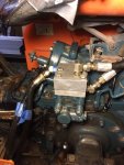
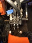
Hello to all and thank you for taking the time to read this request for assistance, this may be a quick answer from the group and I apologize for the long winded story, in bold is the quick question if you need to skip. I have recently registered here on Orange but have scoured a number of previous posts on my issue at hand prior to registration and posting. There may be a thread that I have missed or a simple fix so I apologize if this is repetitive and am more than happy to jump over to one that can answer it. I am also quite new to Kubota, this is my first, I have an L185DT purchased by my father a few years ago from a single owner who bought it in March 1980. It has a FEL and power steering (Kubota brand -PS L9110 and FEL L1200 model) added by the previous owner, in the pictures I post there is the added block with the lines for these. Since purchase, I have only used the FEL for light use on a small farm but have acquired some implements that I'd like to use.

I have done a number of repairs (see below for list of troubleshooting/repairs) and am up to my current problem which is that the 3 point arms will only work while the FEL bucket control lever (right lever) is being engaged (tilting either direction even when fully up). Unfortunately I was not present during purchase to see how the 3 point hitch operates on this tractor, I was just told they did. I am fine with this set up as everything is working, my worry is that this may not be normal and I could be damaging internal components if I continue. Any insight would be most helpful, thank you, A.

Troubleshooting/repair list:
Initially the arms did not work and no combination of anything I tried would make them move. The arms free floated and could be raised by hand but the FEL and PS worked well with no issues making me assume the pump was good. I started simple:

-turned both ways and inbetween the down speed/control knob just under the seat- No movement
-checked the pin at the base of the hydraulic control lever - Intact
-changed hyd fluid and purchased new screen filter - No movement
-pulled the piston under the seat and replaced o-ring and backup ring - No damage/scoring to piston, cylinder wall or rod, no buildup of sludge
I performed a recommended external test on the control valve, where the arms stayed up after turning the control knob to stop and shutting off the tractor. Apparently this would indicated an issue with the control valves inside of the housing.
-pulled the top off of the rear housing under the seat and replaced o-rings to the control valve, some buildup but quite clean, followed the service manual provided on one of these threads. Internal gearing at the arms looked clean and undamaged.
-also pulled the oil pressure assy block off and checked for plugging - all cleaned, no issue noted.
-reattached everything, still no movement in arms
-pulled the loader and power steer assy block off and replaced with original cap- arms worked perfectly
-reassembled block and no movement until finding the above combination to make arms work.
 

Attachments

TheOldHokie

Well-known member
Lifetime Member

Equipment
L3901/LA525, B7200DT/B1630, G2160/RCK60, G2460/RCK60
Apr 6, 2021
8,928
4,668
113
Myersville, MD
windyridgefarm.us
Hello to all and thank you for taking the time to read this request for assistance, this may be a quick answer from the group and I apologize for the long winded story, in bold is the quick question if you need to skip. I have recently registered here on Orange but have scoured a number of previous posts on my issue at hand prior to registration and posting. There may be a thread that I have missed or a simple fix so I apologize if this is repetitive and am more than happy to jump over to one that can answer it. I am also quite new to Kubota, this is my first, I have an L185DT purchased by my father a few years ago from a single owner who bought it in March 1980. It has a FEL and power steering (Kubota brand -PS L9110 and FEL L1200 model) added by the previous owner, in the pictures I post there is the added block with the lines for these. Since purchase, I have only used the FEL for light use on a small farm but have acquired some implements that I'd like to use.

I have done a number of repairs (see below for list of troubleshooting/repairs) and am up to my current problem which is that the 3 point arms will only work while the FEL bucket control lever (right lever) is being engaged (tilting either direction even when fully up). Unfortunately I was not present during purchase to see how the 3 point hitch operates on this tractor, I was just told they did. I am fine with this set up as everything is working, my worry is that this may not be normal and I could be damaging internal components if I continue. Any insight would be most helpful, thank you, A.

Troubleshooting/repair list:
Initially the arms did not work and no combination of anything I tried would make them move. The arms free floated and could be raised by hand but the FEL and PS worked well with no issues making me assume the pump was good. I started simple:

-turned both ways and inbetween the down speed/control knob just under the seat- No movement
-checked the pin at the base of the hydraulic control lever - Intact
-changed hyd fluid and purchased new screen filter - No movement
-pulled the piston under the seat and replaced o-ring and backup ring - No damage/scoring to piston, cylinder wall or rod, no buildup of sludge
I performed a recommended external test on the control valve, where the arms stayed up after turning the control knob to stop and shutting off the tractor. Apparently this would indicated an issue with the control valves inside of the housing.
-pulled the top off of the rear housing under the seat and replaced o-rings to the control valve, some buildup but quite clean, followed the service manual provided on one of these threads. Internal gearing at the arms looked clean and undamaged.
-also pulled the oil pressure assy block off and checked for plugging - all cleaned, no issue noted.
-reattached everything, still no movement in arms
-pulled the loader and power steer assy block off and replaced with original cap- arms worked perfectly
-reassembled block and no movement until finding the above combination to make arms work.
Absolutely not correct. The 3pt should work independent of the loader. Lots of unknowns here but if the 3pt only works when the loader valve is shifted i would guess the tank return and power beyond connections on the loader valve are reversed.

Dan
 

compactfarm

New member

Equipment
L185DT
Jun 29, 2021
4
0
1
VT
Absolutely not correct. The 3pt should work independent of the loader. Lots of unknowns here but if the 3pt only works when the loader valve is shifted i would guess the tank return and power beyond connections on the loader valve are reversed.

Dan
Thank you Dan for the information,
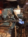
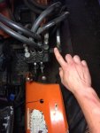
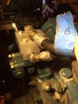
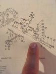
I took a look as I did not mess with any of the lines on the FEL except removing and replacing during my o-ring repairs at the block. I can attach a pic but what I see is the line exits the power beyond connection from the FEL control and directly feeds back to the reservoir T connection. I added two pics with a 'B' to designate the line connections on the block assy to the control, just for further detail. #10 in the diagram is the power beyond/where my finger is pointing. Does this look incorrect and which line should I swap? Will this current setup that I have working cause issues down the road?

Very much appreciated, A.
 

Attachments

TheOldHokie

Well-known member
Lifetime Member

Equipment
L3901/LA525, B7200DT/B1630, G2160/RCK60, G2460/RCK60
Apr 6, 2021
8,928
4,668
113
Myersville, MD
windyridgefarm.us
Thank you Dan for the information,
I took a look as I did not mess with any of the lines on the FEL except removing and replacing during my o-ring repairs at the block. I can attach a pic but what I see is the line exits the power beyond connection from the FEL control and directly feeds back to the reservoir T connection. I added two pics with a 'B' to designate the line connections on the block assy to the control, just for further detail. #10 in the diagram is the power beyond/where my finger is pointing. Does this look incorrect and which line should I swap? Will this current setup that I have working cause issues down the road?

Very much appreciated, A.
The pictures do not tell me anything. In general the connections should be as follow:

1) T on loader valve goes to T on block
2) PB on loader valve goes to whatever port feeds the 3pt.

If those two lines are reversed you will not cause any harm but the 3pt will only work when one or both spools on the loader valve are shifted. A diagram of the ports on the block showing their function would be helpful.
 

compactfarm

New member

Equipment
L185DT
Jun 29, 2021
4
0
1
VT
The pictures do not tell me anything. In general the connections should be as follow:

1) T on loader valve goes to T on block
2) PB on loader valve goes to whatever port feeds the 3pt.

If those two lines are reversed you will not cause any harm but the 3pt will only work when one or both spools on the loader valve are shifted. A diagram of the ports on the block showing their function would be helpful.
Sorry about that Dan,
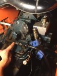
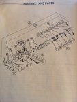
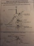
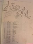
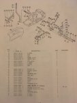
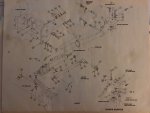
Here are some more images that I have acquired. Thank you again for sticking with me on this.

IMG 2931 is the aftermarket assembly that attaches to the block in IMG 2934
 

Attachments

TheOldHokie

Well-known member
Lifetime Member

Equipment
L3901/LA525, B7200DT/B1630, G2160/RCK60, G2460/RCK60
Apr 6, 2021
8,928
4,668
113
Myersville, MD
windyridgefarm.us
Sorry about that Dan,
Here are some more images that I have acquired. Thank you again for sticking with me on this.

IMG 2931 is the aftermarket assembly that attaches to the block in IMG 2934
Here is a picture of your loader valve with the ports labeled:
  1. Pressure IN should be coming from port on top of the aluminum block
  2. Pressure out should be going to the port on the side of the aluminum block
  3. Tank return should be going to the tee fitting on the top of the transmission.
Dan
 

Attachments

compactfarm

New member

Equipment
L185DT
Jun 29, 2021
4
0
1
VT
Here is a picture of your loader valve with the ports labeled:
  1. Pressure IN should be coming from port on top of the aluminum block
  2. Pressure out should be going to the port on the side of the aluminum block
  3. Tank return should be going to the tee fitting on the top of the transmission.
Dan
Thank you very much again Dan and 007,
Your returned image with markings and explanation were very helpful in placing the correct line. The PB was incorrectly installed to the tank, I switched the Pressure out and Tank return, previous owner must have just used it that way from his installation. Finally have a functioning 3 point system.
Thank you again for getting me over this final hump,
A
 

TheOldHokie

Well-known member
Lifetime Member

Equipment
L3901/LA525, B7200DT/B1630, G2160/RCK60, G2460/RCK60
Apr 6, 2021
8,928
4,668
113
Myersville, MD
windyridgefarm.us
Thank you very much again Dan and 007,
Your returned image with markings and explanation were very helpful in placing the correct line. The PB was incorrectly installed to the tank, I switched the Pressure out and Tank return, previous owner must have just used it that way from his installation. Finally have a functioning 3 point system.
Thank you again for getting me over this final hump,
You are more than welcome.

Dan