help! B8200HST: How does Directional Valve work for hydraulics?

murky

Member
Mar 30, 2012
107
0
16
Vancouver, WA
I was having the tractor picked up this evening for repair, and hastily went to adjust the directional valve (having never done so before) since I have the loader removed.

The label on the tractor (pictured below) says "When the hydraulic outlet A is not in use, turn the directional valve counterclockwise completely. If not the relief valve will operate" (presumably what I should do when the loader is disconnected).

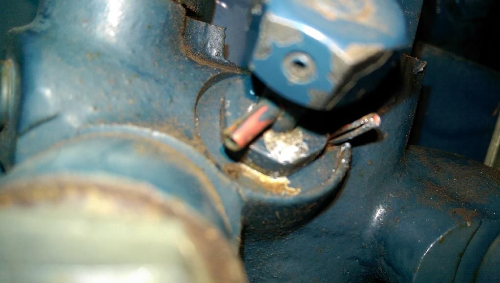
In poor light I thought the pin sticking out of it was a cotter pin preventing it from rotating. So I bent one out of the way thinking this was a screw/bolt that I wanted to turn until it stopped, and found that the valve can turn many revolutions (perhaps indefinitely) in either direction.

Now I see that what I bent out of the way was supposed to be a rotation stop but I still don't understand how it works. In use is is only supposed to be able to turn less than 360 degrees? Are there supposed to be two stops so it can just travel in an arc?

It had been wired in place so it could barely turn at all. I removed the wire.

I need to know what to do with this before I put the loader back on. And will it hurt the tractor to run it how it is now without the loader connected?

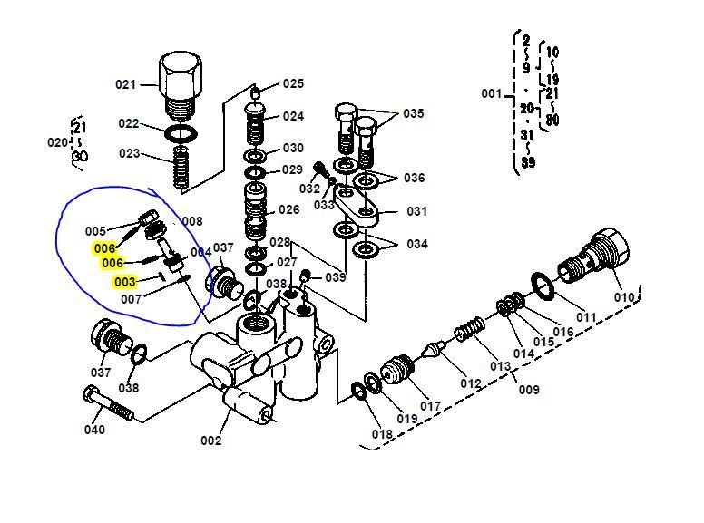
In the third image of the parts diagram 003 and 006 are "SPRING,PIN". And the loader worked great before I messed with anything.
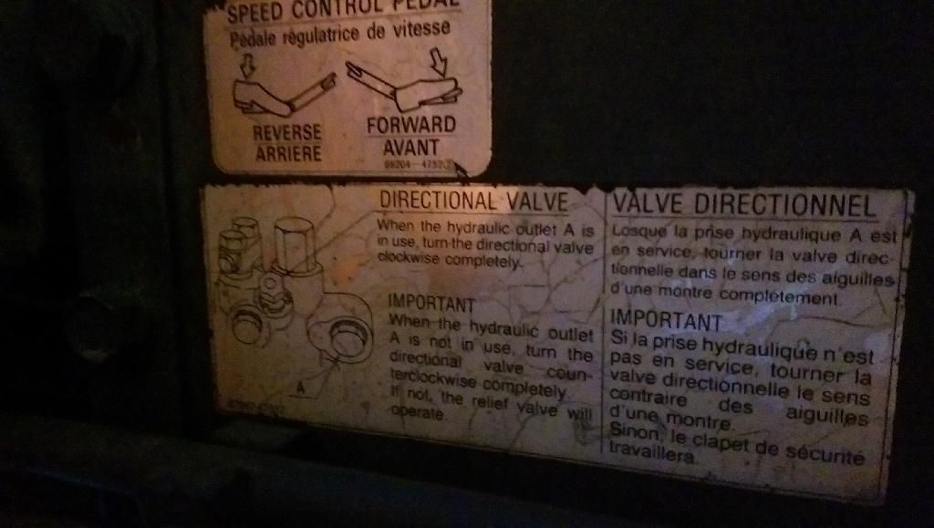


Last edited:

North Idaho Wolfman

Moderator
Staff member
Lifetime Member

Equipment
L3450DT-GST, Woods FEL, B7100 HSD, FEL, 60" SB, 743 Bobcat with V2203, and more
Jun 9, 2013
29,093
5,392
113
Sandpoint, ID
Either pull the bent roll pin out and replace it (best option) or bend it back then follow what the direction say.
It looks like right now you have it halfway between the two positions, so it will be forcing the valve to go into bypass / relief.
 

murky

Member
Mar 30, 2012
107
0
16
Vancouver, WA
Either pull the bent roll pin out and replace it (best option) or bend it back then follow what the direction say.
It looks like right now you have it halfway between the two positions, so it will be forcing the valve to go into bypass / relief.
North Idaho Wolfman,

I really appreciate your willingness to help with requests like this. Thank you.

The pin is bent back so it can function as a stop now.

But Does it matter that it may have been turned 2 or 3 (or more)revolutions while the pin was bent out of the way, or does it just matter the orientation?

And does the one vertical pin on the right of the actual picture of the tractor act as the stop in both directions (clockwise and counterclockwise) or is it just supposed to stop one direction? If one direction, which one and where is the stop supposed to be in the other direction?

Is the pin in the nut on the top supposed to protrude also and stop on something, or is it just holding the nut on or what? I assumed it was a set screw when I first saw it but the parts diagram shows it as the same pin as the large red painted one.

It looks like its been that way for a long time because it is painted over and the exposed end looks smooth.

Also, is allowing the valve to go to relief harmful to the tractor?
 

murky

Member
Mar 30, 2012
107
0
16
Vancouver, WA
Ahhh! I think I understand now what is going on.

There are supposed to be Qty. 2 of the smaller 003 pin. One is broken off. The previous owner must have wired the valve to try and keep it in the loader position. He probably never removed the loader.

So the valve is supposed to swing in an arc and presumably only the position is important (not the number of turns like a screw).

So I will buy some new spring pins and remove the old and seat the new. But now I need to know: Is the big pin supposed to ride in the smaller (about 140 degree) arc in the front shown in red between the smaller pins, or in the back in the larger (about 220 degree arc) shown in blue?

If I have to guess I'd assume the blue arc. If that is right then it looks like I inadvertantly managed to leave it in roughly the correct position for the loader detached.

The red circle shows the broken off small pin location that needs to be replaced.

 
Last edited:

Rob

Member
Lifetime Member

Equipment
B6000DT / B7100DP /B8200DT/L225/Globe PTO Chipper/Lewis Backhoe/huxley TR66
Nov 22, 2009
679
5
18
Leafy England....
Yep, had the exact same problem a while back except both of the stop pins were missing :eek: , i must say i did have a real nightmare getting the old remaining parts of the roll pins out:mad::mad:.
had drill them out very carefully and a size up then put in new larger dia pins.

worked out in the end.
I can honestly say, not one of kubotas better design features this one:(

rob
 

murky

Member
Mar 30, 2012
107
0
16
Vancouver, WA
Yep, had the exact same problem a while back except both of the stop pins were missing :eek: , i must say i did have a real nightmare getting the old remaining parts of the roll pins out:mad::mad:.
had drill them out very carefully and a size up then put in new larger dia pins.

worked out in the end.
I can honestly say, not one of kubotas better design features this one:(

rob
I agree about not being the greatest design feature. I may just thread a tall screw/bolt into the roll pin stub and let it stick up high enough. It is just acting as a peg.

I thought I had added another reply. From looking at the diagram on the tractor it is clear that it is supposed to travel within the smaller red arc. Which means I need to rotate it counterclockwise until it stops on the pin while the loader is off.

The stop for when the loader is on is the one that is missing.
 

North Idaho Wolfman

Moderator
Staff member
Lifetime Member

Equipment
L3450DT-GST, Woods FEL, B7100 HSD, FEL, 60" SB, 743 Bobcat with V2203, and more
Jun 9, 2013
29,093
5,392
113
Sandpoint, ID
Sounds like you have a handle on it now.
Yes not one of their better designs.
 
Last edited: