Determining bevel gear clearance

TheOldHokie

Well-known member
Lifetime Member

Equipment
L3901/LA525, B7200DT/B1630, G2160/RCK60, G2460/RCK60
Apr 6, 2021
8,727
4,468
113
Myersville, MD
windyridgefarm.us
The only pressure on the plasigage will be the rotational force to turn the vertical shaft and the bull gear, which will be very little and the force it takes to force the tooth into the now narrower valley (due to the plastigage taking up some of the room).
I hear what you are saying but I have serious doubts that provides an accurate measurement of lash. But if Kubota says its OK to do it that way then plastigage away.

Dan
 
  • Like
Reactions: 1 user

Henro

Well-known member

Equipment
B2910, BX2200, KX41-2V mini Ex., Beer fridge
May 24, 2019
5,781
2,965
113
North of Pittsburgh PA
Spur gear teeth mainly roll against each other. Spiral bevel gears slide across each other. That is why differential lubricants contain elevated levels of EP additives.

Every gear set has a drive and coast side which is defined relative to the direction of rotation. When you reverse the rotation drive and coast are swapped.

A dial indicator will tell you the exact (almost) distance the gears move at the pitch circle. That is the definition of gear lash and it may vary slightly around a gear due to gear cutting error as the gear is formed.

Machinery's Handbook contains a wealth of information on the topic.

Dan
I don’t know, but doubt gears that last a long time are designed to slide against one another.

Many, maybe most, gears seem to be designed following the principle of the involute curve. The net effect is that this allows the gears to transmit force with minimal slippage between the contact points. Minimum slippage means minimal friction losses, and minimal wear. The contact point between gear teeth actually moves across the faces as the gear turns.

But gears are never manufactured perfectly, and even if they were, they would distort a bit under load, so there would be some rubbing effect occurring, and wear resulting. Lubricants help reduce this wear.

Sometime in the past the lightbulb came on in my mind and I realized this.

Not really trying to debate anything. Just expressing my amazement when I realized most gear surfaces are curved for a reason.

My background is electrical, not mechanical. But I am a bit analytical. LOL
 
  • Like
Reactions: 1 user

TheOldHokie

Well-known member
Lifetime Member

Equipment
L3901/LA525, B7200DT/B1630, G2160/RCK60, G2460/RCK60
Apr 6, 2021
8,727
4,468
113
Myersville, MD
windyridgefarm.us
I don’t know, but doubt gears that last a long time are designed to slide against one another.

Many, maybe most, gears seem to be designed following the principle of the involute curve. The net effect is that this allows the gears to transmit force with minimal slippage between the contact points. Minimum slippage means minimal friction losses, and minimal wear The contact point between gear teeth actually moves across the faces as the gear turns.


My background is electrical, not mechanical. But I am a bit analytical. LOL
I am pretty analytical myself o_O and I have spent some time learning about gears. I understand the geometry of the involute tooth design and why it is used but its not as simple as you think. Here is a brief excerpt from a technical article describing the meshing action of plain spur gears.

When gear teeth mesh, they roll and slide together.

The first point of contact is near the root of the driving tooth and the tip of the driven tooth. As contact between the gear teeth progresses, sliding predominates while rolling is minimized. However, the opposite occurs when mid point tooth contact is reached, and sliding is reduced as rolling predominates. At the pitch line, sliding is zero and rolling is maximized.


As the gears come out of the mesh, sliding progresses


That was authored by Mobil as part of an extended technical analysis of the performance requirements for gear oils.

So even plain involute spur gears slide against one another. That sliding action becomes more pronounced in a plain spiral bevel gear set where there is more overlap of tooth mesh. Hypoid spiral bevel gears produce even more tooth overlap and even more sliding. Worm gears are worse yet. All of those designs are used with the expectation the gears will "last".

And as I said earlier that's why spiral bevel gears require a lubricant with elevated levels of extreme pressure additives (API GL4). Hypoid spiral bevel gears require even higher EP treat rates (API GL5).

Dan
 
Last edited:
  • Like
Reactions: 1 users

ejb11235

Well-known member

Equipment
BX23S, Braber BBR4G 4' Box Blade & LRM5G 5' landscape rake
Jan 20, 2022
452
327
63
Seattle, WA, USA
I am pretty analytical myself o_O and I have spent some time learning about gears. I understand the geometry of the involute tooth design and why it is used but its not as simple as you think. Here is a brief excerpt from a technical article describing the meshing action of plain spur gears.

When gear teeth mesh, they roll and slide together.

The first point of contact is near the root of the driving tooth and the tip of the driven tooth. As contact between the gear teeth progresses, sliding predominates while rolling is minimized. However, the opposite occurs when mid point tooth contact is reached, and sliding is reduced as rolling predominates. At the pitch line, sliding is zero and rolling is maximized.


As the gears come out of the mesh, sliding progresses


That was authored by Mobil as part of an extended technical analysis of the performance requirements for gear oils.

So even plain involute spur gears slide against one another. That sliding action becomes more pronounced in a plain spiral bevel gear set where there is more overlap of tooth mesh. Hypoid spiral bevel gears produce even more tooth overlap and even more sliding. Worm gears are worse yet. All of those designs are used with the expectation the gears will "last".

And as I said earlier that's why spiral bevel gears require a lubricant with elevated levels of extreme pressure additives (API GL4). Hypoid spiral bevel gears require even higher EP treat rates (API GL5).

Dan
Damn you guys ... now I'm sitting here pondering the mathematical definition of sliding versus rolling. The best I can come up with is something like:

assume two meshed gears called P and Q, with P representing the set of all points on gear P and Q representing the set of all points on gear Q

if r represents the angle of rotation of gear P,
then a contact patch at rotation r exists C(r)

C(r) = [ (p1,q1), (p2,q2) ...] where pi and qi are in P and Q respectively and pi and qi are touching

Then, the gears are rolling if, for all values of r (within one tooth meshing), for all (p1,q1) in C(r) and (p2,q2) in C(r), if p1=p2 then q1=q2

somehow I don't think set theory is a very useful way to approach this problem ... normals and tangents seem more appropriate, but I can't formulate anything...it's been too long since I was in college and had to really think
 
Last edited:

TheOldHokie

Well-known member
Lifetime Member

Equipment
L3901/LA525, B7200DT/B1630, G2160/RCK60, G2460/RCK60
Apr 6, 2021
8,727
4,468
113
Myersville, MD
windyridgefarm.us
Damn you guys ... now I'm sitting here pondering the mathematical definition of sliding versus rolling. The best I can come up with is something like:

assume two meshed gears called P and Q, with P representing the set of all points on gear P and Q representing the set of all points on gear Q

if r represents the angle of rotation of gear P,
then a contact patch at rotation r exists C(r)

C(r) = [ (p1,q1), (p2,q2) ...] where pi and qi are in P and Q respectively and pi and qi are touching

Then, the gears are rolling if, for all values of r (within one tooth meshing), for all (p1,q1) in C(r) and (p2,q2) in C(r), if p1=p2 then q1=q2

somehow I don't think set theory is a very useful way to approach this problem ... normals and tangents seem more appropriate, but I can't formulate anything...it's been too long since I was in college and had to really think
Set theory was a distant place and a long time ago for me. Its actually just simple geometry. In furtherance of the mother of all thread hijacks:

Dan

1656847670221.png
 
Last edited:
  • Like
Reactions: 1 users

ejb11235

Well-known member

Equipment
BX23S, Braber BBR4G 4' Box Blade & LRM5G 5' landscape rake
Jan 20, 2022
452
327
63
Seattle, WA, USA
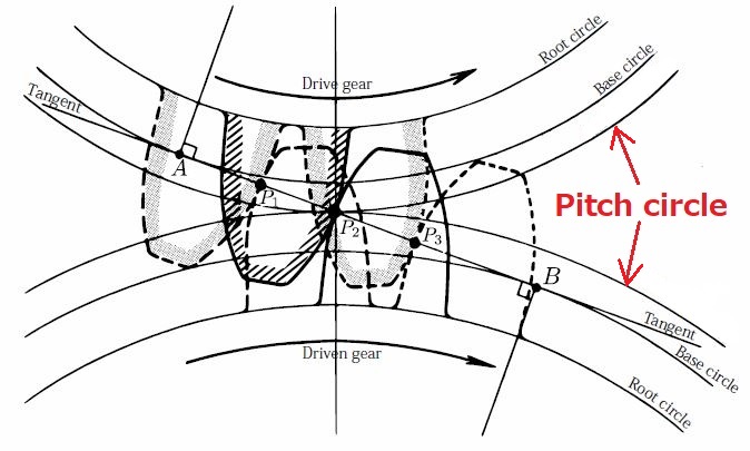
The first point of contact is near the root of the driving tooth and the tip of the driven tooth. As contact between the gear teeth progresses, sliding predominates while rolling is minimized. However, the opposite occurs when mid point tooth contact is reached, and sliding is reduced as rolling predominates. At the pitch line, sliding is zero and rolling is maximized.
Are you using the term "pitch line" synonymous with "pitch circle"?
I found a definition of "pitch line" in the context of a linear gear, and it seemed to be analogous to the term "pitch circle" when used to describe a circular gear.

1656864608057.png 1656864674800.png
 

TheOldHokie

Well-known member
Lifetime Member

Equipment
L3901/LA525, B7200DT/B1630, G2160/RCK60, G2460/RCK60
Apr 6, 2021
8,727
4,468
113
Myersville, MD
windyridgefarm.us
Are you using the term "pitch line" synonymous with "pitch circle"?
I found a definition of "pitch line" in the context of a linear gear, and it seemed to be analogous to the term "pitch circle" when used to describe a circular gear.

View attachment 82881 View attachment 82882
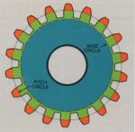
Pitch circle is the reference geometry of a gear or pulley. It is the basis for lots of gear calculations - most notably the diametral or circular pitch (size) of the tooth and is used to compute gear spacing e.g. add the pitch diameters and divide by two to get the center spacing of the gears. That makes the pitch circles tangent to one another but provides no gear lash. By increasing the spacing you create gear lash.

For involute spur gears the pitch circle is the circular boundary between the addendum and dedendum portions of the tooth form.

Dan

What is a pitch circle ?
The pitch circle is the circumference used as the standard of a pitch to express the size of gear teeth.
Its length is the circular pitch multiplied by the number of teeth.
The pitch circle is an imaginary circle and unlike the tip circle and root circle, it cannot be seen.

The diagram below graphically shows the pitch circle.

pitch circle
 
Last edited:

Henro

Well-known member

Equipment
B2910, BX2200, KX41-2V mini Ex., Beer fridge
May 24, 2019
5,781
2,965
113
North of Pittsburgh PA
I am pretty analytical myself o_O and I have spent some time learning about gears. I understand the geometry of the involute tooth design and why it is used but its not as simple as you think. Here is a brief excerpt from a technical article describing the meshing action of plain spur gears.

When gear teeth mesh, they roll and slide together.

The first point of contact is near the root of the driving tooth and the tip of the driven tooth. As contact between the gear teeth progresses, sliding predominates while rolling is minimized. However, the opposite occurs when mid point tooth contact is reached, and sliding is reduced as rolling predominates. At the pitch line, sliding is zero and rolling is maximized.


As the gears come out of the mesh, sliding progresses


That was authored by Mobil as part of an extended technical analysis of the performance requirements for gear oils.

So even plain involute spur gears slide against one another. That sliding action becomes more pronounced in a plain spiral bevel gear set where there is more overlap of tooth mesh. Hypoid spiral bevel gears produce even more tooth overlap and even more sliding. Worm gears are worse yet. All of those designs are used with the expectation the gears will "last".

And as I said earlier that's why spiral bevel gears require a lubricant with elevated levels of extreme pressure additives (API GL4). Hypoid spiral bevel gears require even higher EP treat rates (API GL5).

Dan
Thanks for that!

I guess being electrical in background I gave the mechanical guys more credit than they deserved. LOL

Obviously, there is slipping between the gear surfaces except at the pitch point.

Interesting thing is that (I suppose) due to the involute curve of the gear faces, the relative amount of slippage is less than if some other physical gear configuration was used.

The point of contact between the surfaces is constantly moving, as the gear turns. It moves towards the pitch point from one side, and away from the pitch point on the other side.

But even more interesting is that at the pitch point, there is no slipping. And that the speed of slipping between the surfaces decreases as the contact point approaches the pitch point, and increases as the contact point leaves the pitch point.

Learned something today:

1. Gear surfaces do move with respect to each other, and slide against each other, at least if lubricant is insufficient.
2. Be careful giving mechanical guys too much credit! LOL
 

TheOldHokie

Well-known member
Lifetime Member

Equipment
L3901/LA525, B7200DT/B1630, G2160/RCK60, G2460/RCK60
Apr 6, 2021
8,727
4,468
113
Myersville, MD
windyridgefarm.us
Thanks for that!

I guess being electrical in background I gave the mechanical guys more credit than they deserved. LOL

Obviously, there is slipping between the gear surfaces except at the pitch point.

Interesting thing is that (I suppose) due to the involute curve of the gear faces, the relative amount of slippage is less than if some other physical gear configuration was used.

The point of contact between the surfaces is constantly moving, as the gear turns. It moves towards the pitch point from one side, and away from the pitch point on the other side.

But even more interesting is that at the pitch point, there is no slipping. And that the speed of slipping between the surfaces decreases as the contact point approaches the pitch point, and increases as the contact point leaves the pitch point.

Learned something today:

1. Gear surfaces do move with respect to each other, and slide against each other, at least if lubricant is insufficient.
2. Be careful giving mechanical guys too much credit! LOL
Once again you are quick on the uptake. Dont bash the mechanical guys too much (I am not one) - there is just a lot of bad science/engineering floating around the Internet.

Dan
 

Henro

Well-known member

Equipment
B2910, BX2200, KX41-2V mini Ex., Beer fridge
May 24, 2019
5,781
2,965
113
North of Pittsburgh PA
Once again you are quick on the uptake. Dont bash the mechanical guys too much (I am not one) - there is just a lot of bad science/engineering floating around the Internet.

Dan
I was just joking. In my past life in heavy industry, we had operators, mechanical, and electrical people.

Each thought they were the cat's meow. I came to realize each were equal to the others in their own way, and none were better than the other...

Took quite a while to get to that point though...LOL
 

TheOldHokie

Well-known member
Lifetime Member

Equipment
L3901/LA525, B7200DT/B1630, G2160/RCK60, G2460/RCK60
Apr 6, 2021
8,727
4,468
113
Myersville, MD
windyridgefarm.us
T
I was just joking. In my past life in heavy industry, we had operators, mechanical, and electrical people.

Each thought they were the cat's meow. I came to realize each were equal to the others in their own way, and none were better than the other...

Took quite a while to get to that point though...LOL
That philosophy is way to reasonable for today's world :devilish:

Dan
 

ejb11235

Well-known member

Equipment
BX23S, Braber BBR4G 4' Box Blade & LRM5G 5' landscape rake
Jan 20, 2022
452
327
63
Seattle, WA, USA
1. Gear surfaces do move with respect to each other, and slide against each other, at least if lubricant is insufficient.
I think the point we've been arriving at is that sliding between gear surfaces is a function of geometry, not lubrication. The lubricant must be designed/spec'd propertly because there is sliding, both to provide the necessary lubrication to the gears, but also provide longevity to the lubricant.
 
  • Like
Reactions: 1 user

ejb11235

Well-known member

Equipment
BX23S, Braber BBR4G 4' Box Blade & LRM5G 5' landscape rake
Jan 20, 2022
452
327
63
Seattle, WA, USA
Pitch circle is the reference geometry of a gear or pulley. It is the basis for lots of gear calculations - most notably the diametral or circular pitch (size) of the tooth and is used to compute gear spacing e.g. add the pitch diameters and divide by two to get the center spacing of the gears. That makes the pitch circles tangent to one another but provides no gear lash. By increasing the spacing you create gear lash.
Dan -- I think you left out one important aspect of the pitch circles. Correct me if I'm wrong, but don't they determine the gear ratio? Specifically, aren't the velocities of gear 1 and gear 2 equal at the pitch circle?

For example, if r1 is the radius of gear 1 in inches at the pitch circle, then the velocity (in inches/sec) is:

v1 = (2*pi*r1) * RPM/60

Similarly, v2 = ...

Since v1=2, RPM2 can be calculated and thus provide the gear ratio.

I'm still unclear exactly 'when and where" sliding occurs. I get the idea that sliding is at a maximum at the very beginning and end of tooth engagement, but as you've pointed out, different types of gears exhibit different amounts of sliding (e.g. a worm gear is 100% sliding). And it's not clear to me how, even just looking at spur gears, the shape of the gear teeth affect the amount of sliding.

Eric
 

TheOldHokie

Well-known member
Lifetime Member

Equipment
L3901/LA525, B7200DT/B1630, G2160/RCK60, G2460/RCK60
Apr 6, 2021
8,727
4,468
113
Myersville, MD
windyridgefarm.us
Dan -- I think you left out one important aspect of the pitch circles. Correct me if I'm wrong, but don't they determine the gear ratio? Specifically, aren't the velocities of gear 1 and gear 2 equal at the pitch circle?

For example, if r1 is the radius of gear 1 in inches at the pitch circle, then the velocity (in inches/sec) is:

v1 = (2*pi*r1) * RPM/60

Similarly, v2 = ...

Since v1=2, RPM2 can be calculated and thus provide the gear ratio.

I'm still unclear exactly 'when and where" sliding occurs. I get the idea that sliding is at a maximum at the very beginning and end of tooth engagement, but as you've pointed out, different types of gears exhibit different amounts of sliding (e.g. a worm gear is 100% sliding). And it's not clear to me how, even just looking at spur gears, the shape of the gear teeth affect the amount of sliding.

Eric
This discussion is rapidly approaching off topic status. You are pushing the limits of my knowledge with those questions but I will have a whack at answering them
  1. Practically speaking gear ratio is determined by tooth counts,. Tooth counts and size (pitch) determine pitch circle. Or is that the other way around? Sort of a metaphysical question.
  2. This concept of sliding is a bit hard to describe in English.. As previously shown the spur gear slides for the entire length of mesh with the exception of the pitch point. What changes is the delta in the velocities of the moving parts at the contact point. So "sliding" is not increasing" or decreasing. - the surface speed of the slide is increasing and decreasing. Henro picked up on that right off the bat (y)
  3. Increasing and decreasing lash will lengthen or shorten that mesh distance and the amount of the sliding.
  4. Another metric we have not discussed is contact ratio. This is defined as the average number of teeth that are in mesh during a revolution and a number of gear cutting variables like addendum and dedendum height affect that ratio. If the contact ratio is less than 1 the gears experience periods where they are not in mesh. - really bad for smooth power trasnmission but it will reduce the amount of sliding. Similarly if we design the tooth such that we have a contact ratio of 1.2 we increase the power transmission capacity of the gear set but we also increase the amount of sliding.
  5. Enter spiral bevel and hypoid gear teeth. These designs significantly increase the contact ratio of the gear set. This makes for very smooth operation and high power transmission but at the expense of added heat and sliding wear.
That's more than I really "know" but its the best I can offer.

Dan
 
Last edited:
  • Like
Reactions: 1 user

Henro

Well-known member

Equipment
B2910, BX2200, KX41-2V mini Ex., Beer fridge
May 24, 2019
5,781
2,965
113
North of Pittsburgh PA
I think the point we've been arriving at is that sliding between gear surfaces is a function of geometry, not lubrication. The lubricant must be designed/spec'd propertly because there is sliding, both to provide the necessary lubrication to the gears, but also provide longevity to the lubricant.
I believe this is true, BUT there is no physical sliding if a lubricant film exists between the two surfaces.

Yes, there is a difference in speed of movement between the two surfaces, but they do not interact due to the lubricant between them isolating them from each other.

Of course, this assumes the lubricant is effective. Otherwise there will certainly be interaction between the surfaces.
 
Last edited:

ejb11235

Well-known member

Equipment
BX23S, Braber BBR4G 4' Box Blade & LRM5G 5' landscape rake
Jan 20, 2022
452
327
63
Seattle, WA, USA
I believe this is true, BUT there is no physical sliding if a lubricant film exists between the two surfaces.

Yes, there is a difference is speed of movement between the two surfaces, but they do not interact due to the lubricant between them isolating them from each other.

Of course, this assumes the lubricant is effective. Otherwise there will certainly be interaction between the surfaces.
Got it. I was coming from the perspective of "how does the gear design affect the required properties of the lubricant", and you were more about "what's happening to the gears assuming that the lubricant is working".

@TheOldHokie you posted an empty reply to my post. I look forward to reading whatever it was you were going to say.
 
  • Like
Reactions: 1 user

TheOldHokie

Well-known member
Lifetime Member

Equipment
L3901/LA525, B7200DT/B1630, G2160/RCK60, G2460/RCK60
Apr 6, 2021
8,727
4,468
113
Myersville, MD
windyridgefarm.us
I believe this is true, BUT there is no physical sliding if a lubricant film exists between the two surfaces.

Yes, there is a difference in speed of movement between the two surfaces, but they do not interact due to the lubricant between them isolating them from each other.

Of course, this assumes the lubricant is effective. Otherwise there will certainly be interaction between the surfaces.
I don't know 100% for sure but I think the sliding mainly occurs in mixed or boundary lubrication regimes- direct metal to metal contact - no or very little oil film. The surface speed needed to form a full hydrodynamic film does not exist. That is certainly true in the case of heavily loaded spiral bevel and hypoid gears.

Dan