Hello. My name is Tom. I purchased a B6100HST-D 1980's tractor last year and restored it from the tires up. It now runs beautifully, like a new tractor. Just for the hydraulics:
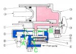
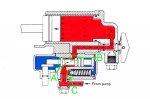
This tractor has a Hydraulic pump, Control valve(open center)...Gravity fed down & diverter valve. The diverter valve switches pressure from the control valve to either the 3 pt hitch or front implement which I have a snow blade.
When I operate the system for either the 3pt or the blade I get a squealing/chatter noise during the 2nd third of the travel distance of the lever. during this period the implement does not move. at the last 3rd of distance of lever travel the implement jumps to its full up position. So in summary its all or nothing. During the squealing noise I have measured less than 100 psi of pressure to the implement. When the squealing stops and the implement is indeed moving(quite fast), the pressure is 1700psi.
I have installed a new Kubota Hydraulic pump and new Kubota control valve assembly. I renewed all of the O-rings in the diverter valve. The hydraulic suction screens were replaced. The fluid replaced twice. With the new hydraulic valve installed, I can now move the implement slowly but only with the hydraulic system squealing and making a lot of noise. Maybe this is normal? The lever will even stay in this position by itself as long as I move it there slowly... it will stay at the 2/3 distance position back and the implement will move slowly up until it reaches max up and then the lever will automatically center itself. So this behavior is different than the old valve. But like I said while in this position (implement moving slowly), the system squeals and chatters.
I feel like I should have more precision control of the implements. Should I not be able to raise these implements slowly and controlled? Is this normal operation(squealing)?
Any one with experience on a B6100 please HELP. Thank you, much appreciated. I'm extemely curious to understand this tractors Hydraulic ailment.