B6100HST-D Hydraulic Issue

tommaso12000

New member
Jun 5, 2016
9
0
0
hollywood, md
Hello. My name is Tom. I purchased a B6100HST-D 1980's tractor last year and restored it from the tires up. It now runs beautifully, like a new tractor. Just for the hydraulics:

This tractor has a Hydraulic pump, Control valve(open center)...Gravity fed down & diverter valve. The diverter valve switches pressure from the control valve to either the 3 pt hitch or front implement which I have a snow blade.

When I operate the system for either the 3pt or the blade I get a squealing/chatter noise during the 2nd third of the travel distance of the lever. during this period the implement does not move. at the last 3rd of distance of lever travel the implement jumps to its full up position. So in summary its all or nothing. During the squealing noise I have measured less than 100 psi of pressure to the implement. When the squealing stops and the implement is indeed moving(quite fast), the pressure is 1700psi.

I have installed a new Kubota Hydraulic pump and new Kubota control valve assembly. I renewed all of the O-rings in the diverter valve. The hydraulic suction screens were replaced. The fluid replaced twice. With the new hydraulic valve installed, I can now move the implement slowly but only with the hydraulic system squealing and making a lot of noise. Maybe this is normal? The lever will even stay in this position by itself as long as I move it there slowly... it will stay at the 2/3 distance position back and the implement will move slowly up until it reaches max up and then the lever will automatically center itself. So this behavior is different than the old valve. But like I said while in this position (implement moving slowly), the system squeals and chatters.

I feel like I should have more precision control of the implements. Should I not be able to raise these implements slowly and controlled? Is this normal operation(squealing)?

Any one with experience on a B6100 please HELP. Thank you, much appreciated. I'm extemely curious to understand this tractors Hydraulic ailment.
 

North Idaho Wolfman

Moderator
Staff member
Lifetime Member

Equipment
L3450DT-GST, Woods FEL, B7100 HSD, FEL, 60" SB, 743 Bobcat with V2203, and more
Jun 9, 2013
30,249
6,408
113
Sandpoint, ID
This tractor has a Hydraulic pump, Control valve(open center)...Gravity fed down & diverter valve. The diverter valve switches pressure from the control valve to either the 3 pt hitch or front implement which I have a snow blade.
Just by reading this, here is your problem.
You don't need or want a diverter block if it's not hooked up right, you want the snow plow control to be in line with the three point controls, so that both will work all the time, you should have it where it diverts to the snow plow control when connected but it still must return to control the three point. The reason for this is the pressure relief valve for the system is after the three point control.
 

tommaso12000

New member
Jun 5, 2016
9
0
0
hollywood, md
Thank you for the response! The diverted valve is built into the tractor.. it also serves as the head for the 3pt piston. The control valve contains the high pressure relief valve.
 

torch

Well-known member

Equipment
B7100HSD, B2789, B2550, B4672, 48" cultivator, homemade FEL and Cab
Jun 10, 2016
2,620
869
113
Muskoka, Ont.
I have a B7100 with similar symptoms. Here's what I think is happening.

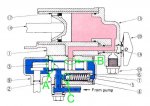
In the neutral position, oil flows from the pump through the spool valve at A and back into the tank. The 3 pt hitch (or auxiliary cylinder) maintains position since the spool valve is closed at B. As there is no opposition to flow, no pressure is built up, so the relief valve is closed at C.


Spool Valve in Neutral Position

(I assume your plow cylinder is connected to the port at 16?)

When the spool valve is moved to the lift position, A must close first. If B opened before A closed, then fluid from the piston would return to the tank through A and the 3 pt hitch would initially drop instead of rise until the lever was moved enough to close A.


Spool Valve in Lift Position

When the lever is in that mid-point position and both A and B are closed, the fluid from the pump has nowhere to go. The pressure quickly rises from near-0 to ~1700psi, forcing the relief valve to open, bleeding pressure by flowing fluid through C. Since the relief valve seat is just a ball, the pressure drops rapidly and the valve may be closing again. This fluid flow and/or rapid fluttering of the relief valve is the source of the squealing noise.

If Kubota had chosen a more gradual relief valve design, I think the transition could be less dramatic and better controlled. But it is what it is. Better control can be achieved by throttling down the engine when operating the 3ph (or accessory).

In the case of the accessory plow cylinder, there are actually two other options that I can think of. A larger diameter cylinder holds more fluid and so extends slower at a given RPM. The flip side is that the larger diameter cylinder exerts a lot more force at a given pressure, so a bigger cylinder could bend or break whatever it's attached to!

Even more expensive than installing a bigger cylinder for the accessory would be to add an aftermarket spool valve (with "power beyond" feature) fed via a new hydraulic block at the right side of the engine. That's how my front end loader is powered and the loader valve is no where near as touchy as the 3ph.
 

Attachments

Last edited:

tommaso12000

New member
Jun 5, 2016
9
0
0
hollywood, md
Thanks Torch. That sounds like a pretty sound theory. My front blade is connected to 16.

It was my understanding that when calling for the implement to move slowly a smaller amount of pressure from the hydraulic system is required. In order to get a smaller amount of pressure, "A" would be partially closed and so would "B". When "A" is fully closed and "B" is fully open then full pressure is available. This would cause the implement to move fast and forcefully(dependent on weight of implement). My front blade only weighs approximately 200lbs.

I'm a little confused about the mid position. I thought that the control valve had 3 positions (functions). Back(Lift), Mid(neutral), Fwd(lower). The understanding that I have is the lift function would close "A" and open "B". This transition would gradually allow less fluid to flow to the tank and more to flow to the piston. Once "A" is fully closed and "B" is fully open and the piston is at the end of its travel then fluid is routed through "C" the high pressure relief valve is active (only while holding the lever back).

The neutral function "B" & "C" are closed and "A" is open allowing fluid to constantly return to the tank.

The lower function allows fluid to flow back from "B" to "A". This allows the implement to drop with gravity as the fluid from the piston is routed back to the tank.

This is how I thought it worked. I've just recently started reading about the operation of hydraulic systems. I am trying to understand this more accurately. The diagrams were awesome, can you give me the link to those? Thanks.
 

tommaso12000

New member
Jun 5, 2016
9
0
0
hollywood, md
One more thing: My control valve has 2 ports on the side which mounts to the tractor. each contains an O ring. One port is identified as "B" in the diagram. The other port must be the return to the tank, I'm guessing it is represented by "A" in the diagram?
 

North Idaho Wolfman

Moderator
Staff member
Lifetime Member

Equipment
L3450DT-GST, Woods FEL, B7100 HSD, FEL, 60" SB, 743 Bobcat with V2203, and more
Jun 9, 2013
30,249
6,408
113
Sandpoint, ID
After your reply and re-reading your first post.
Yes it's normal as that model does not have a proportional valve, it's either on or off.
 

torch

Well-known member

Equipment
B7100HSD, B2789, B2550, B4672, 48" cultivator, homemade FEL and Cab
Jun 10, 2016
2,620
869
113
Muskoka, Ont.
It was my understanding that when calling for the implement to move slowly a smaller amount of pressure from the hydraulic system is required.
I think it is more accurate to say that a smaller flow rate is required to move the cylinder slowly. Pressure influences the amount of force the cylinder can apply, flow rate influences the speed of cylinder travel. Of course, for a given orifice size, the flow rate is directly proportional to the pressure.

In order to get a smaller amount of pressure, "A" would be partially closed and so would "B". When "A" is fully closed and "B" is fully open then full pressure is available. This would cause the implement to move fast and forcefully(dependent on weight of implement). My front blade only weighs approximately 200lbs.
Again, we must be careful not to confuse "flow rate" and "pressure". If the flow rate was constant, the system could probably be engineered to work that way. However, the flow rate varies with the engine rpm, so the physical sizes of "A" and "B" would have to vary to maintain that relationship. In other words, I think the system could be engineered to work that way at any specific RPM, but would not achieve the required balance at any other RPM.

It's much simpler to close "A" completely, allow "C" to limit the pressure and vary "B" to control the flow rate into the cylinder, and I believe that is the route that Kubota's engineers chose. But I'm not an expert!

I'm a little confused about the mid position. I thought that the control valve had 3 positions (functions). Back(Lift), Mid(neutral), Fwd(lower).
Yes.

The understanding that I have is the lift function would close "A" and open "B". This transition would gradually allow less fluid to flow to the tank and more to flow to the piston. Once "A" is fully closed and "B" is fully open and the piston is at the end of its travel then fluid is routed through "C" the high pressure relief valve is active (only while holding the lever back).
Again, I believe "A" fully closes before "B" begins to open, as described above. "C" will open anytime the flow rate from the pump exceeds the capacity of "A"+"B", which is what causes the pressure to rise.

The neutral function "B" & "C" are closed and "A" is open allowing fluid to constantly return to the tank.

The lower function allows fluid to flow back from "B" to "A". This allows the implement to drop with gravity as the fluid from the piston is routed back to the tank.
Yes and Sort of. The fluid from the piston does not travel back through "A", but does end up getting dumped back into the tank. That return path is via the "adjusting bolt", which controls the return flow rate to control the speed of lowering.

The diagrams were awesome, can you give me the link to those? Thanks.
The diagrams are from the Kubota WSM for the B6100 and B7100 HST models. I scanned it into an indexed PDF and provided a copy to kubotabooks.com. You can d/l it here: http://kubotabooks.com/AutoIndex/in...wners Manuals/&file=B7100HST_WSM_complete.pdf . The system is outlined in section M, Hydraulics, which is a separate system from section G, New HST.

The designations "A" "B" and "C" were added by me for this conversation only. They are not designated as such on the Kubota documents.
 
Last edited: