Let me start off by saying that I have very little tractor knowledge. I recently done some trading for a Kubota b6000 tractor that came with a blade on the front and a trencher on the back. It also has a creeper gear installed. I noticed before I removed the trencher that the lifting lever had to be in the back position (which it had a spring on it also) for the hydraulics to work for the trencher and front blade. I removed the trencher and am trying to round up the 3 point hitch components and have now noticed that the new lifting arms that I purchased are not moving when the lever is pushed forward or backwards. However the lever has to be pulled all the way back for the front blade hydraulics to function. How can I make the lever work the lifting arms for the 3 point hitch. Thanks ahead for all the information.
B6000 lifting arms not operating
- Thread starter Leetrfd
- Start date
North Idaho Wolfman
Moderator
Staff member
Lifetime Member
Equipment
L3450DT-GST, Woods FEL, B7100 HSD, FEL, 60" SB, 743 Bobcat with V2203, and more
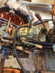
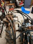
Going to need pictures of how the hydraulics are hooked up.
Sounds like the flow for the front hydraulics is the three point being rerouted to run it.
Sounds like the flow for the front hydraulics is the three point being rerouted to run it.
There are two levers on a plate that controls the front blade above the rear wheel that these two lines run to.Going to need pictures of how the hydraulics are hooked up.
Sounds like the flow for the front hydraulics is the three point being rerouted to run it.
Attachments
-
631.5 KB Views: 110
TheOldHokie
Well-known member
Lifetime Member
Equipment
L3901/LA525, B7200DT/B1630, G2160/RCK60, G2460/RCK60
That is a very special purpose top cover. I have never seen it before and I have no real knowledge of how it works.There are two levers on a plate that controls the front blade above the rear wheel that these two lines run to.
That said based on your description and the picture it seems likely the hose coming out the rear is lift cylinder pressure going to the external hydraulics and the hose going into the tee is return oil. When you raise the position control lever the oil flow that normally operates the lift cylinder and raises the lift arms is routed out the rear hose. I don't see any lift arms or signs of a rockshaft in that picture. I see a shifter lever for the creeper transmission but not the second lever you are describing - where is it and what are you expecting to move?
Dan
Last edited:
Russell King
Well-known member
Lifetime Member
Equipment
L185F, Modern Ag Competitor 4’ shredder, Rhino tiller, rear dirt scoop
Take more pictures of the other ends of the hydraulic lines after putting colored tape at each end of the lines to help us keep track of what goes in and out of the system. Back away a bit so more information is provided in the pictures. Also try to be careful in your description since there are four hoses showing but you said “these two lines”. That is confusing to me at best.
i believe that you mean there are two levers outside of the picture above that control the blade. And the two hoses on the bottom of the picture run to that valve with two levers?
and for NIW: have the picture posting rules for new members change from the past that required 5 posts before they can post pictures?
TheOldHokie
Well-known member
Lifetime Member
Equipment
L3901/LA525, B7200DT/B1630, G2160/RCK60, G2460/RCK60
You can always link hosted images.Take more pictures of the other ends of the hydraulic lines after putting colored tape at each end of the lines to help us keep track of what goes in and out of the system. Back away a bit so more information is provided in the pictures. Also try to be careful in your description since there are four hoses showing but you said “these two lines”. That is confusing to me at best.
i believe that you mean there are two levers outside of the picture above that control the blade. And the two hoses on the bottom of the picture run to that valve with two levers?
and for NIW: have the picture posting rules for new members change from the past that required 5 posts before they can post pictures?
Dan
North Idaho Wolfman
Moderator
Staff member
Lifetime Member
Equipment
L3450DT-GST, Woods FEL, B7100 HSD, FEL, 60" SB, 743 Bobcat with V2203, and more
Yes, I think they have changed when we changed software, but I could be wrong.NIW: have the picture posting rules for new members change from the past that required 5 posts before they can post pictures?
North Idaho Wolfman
Moderator
Staff member
Lifetime Member
Equipment
L3450DT-GST, Woods FEL, B7100 HSD, FEL, 60" SB, 743 Bobcat with V2203, and more
Need to see the valve that the single newer hose off the front of the three point cylinder goes to.There are two levers on a plate that controls the front blade above the rear wheel that these two lines run to.
I bet you will have to add a shut off to that line to make the three point work it work properly.
There are manuals for the B6000 at Kubotabooks. The shop manual shows/describes a diverter valve which i don't see on OP's machine. More pictures would help understand the situation.
North Idaho Wolfman
Moderator
Staff member
Lifetime Member
Equipment
L3450DT-GST, Woods FEL, B7100 HSD, FEL, 60" SB, 743 Bobcat with V2203, and more
Yes the cover with a diverter valve was an option.There are manuals for the B6000 at Kubotabooks. The shop manual shows/describes a diverter valve which i don't see on OP's machine. More pictures would help understand the situation.
In this case it really would be just a matter of adding a shut off valve to that line to make the three point work.
TheOldHokie
Well-known member
Lifetime Member
Equipment
L3901/LA525, B7200DT/B1630, G2160/RCK60, G2460/RCK60
I am not familiar with that model but to me it looks like the entire top cover has been replaced with some sort of special purpose trencher conversion. I dont see any signs of a 3pt - where are the lift arms and rock shaft?Yes the cover with a diverter valve was an option.
In this case it really would be just a matter of adding a shut off valve to that line to make the three point work.
I would also be cautious about blocking the outlet not knowing what if any relief is in the circuit.
Dan
TheOldHokie
Well-known member
Lifetime Member
Equipment
L3901/LA525, B7200DT/B1630, G2160/RCK60, G2460/RCK60
Yes - in particular a picture from a greater distance showing a more complete view of the cover and its relationship to the redt of the tractor.There are manuals for the B6000 at Kubotabooks. The shop manual shows/describes a diverter valve which i don't see on OP's machine. More pictures would help understand the situation.
Dan
North Idaho Wolfman
Moderator
Staff member
Lifetime Member
Equipment
L3450DT-GST, Woods FEL, B7100 HSD, FEL, 60" SB, 743 Bobcat with V2203, and more
The front cover of the three point cylinder is where the new hydraulic hose is located.
the three point arms are off camera to the left.
Forget about the gear reduction box, it has no bearing on this issue, it simply slows the drive down.
On this model the relief valve is in the three point control, it happens before the Three point output, which in this case is being redirected to the valve for the blade.
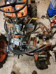
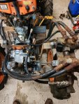
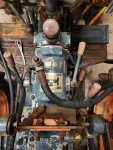
My apologies on the lack of better pictures and better clarification. I am new to the tractor world and was on duty at the firehouse and posted that first post on the fly. I have found the lifting arms and they are not currently on the tractor. Both cylinders on the front blade work perfect as long as the raising and lowering lever is in the back position. However the splines on the lifting arms do not move at any point. I have read the previous post about putting a valve on the supply line (newer line) in the picture to make the lifting arms work, but just wanted to give you guys better pictures to make sure of that before I mess something up. Thank y'all so much for the input and I appreciate the add on this page.
Attachments
-
793.4 KB Views: 86
-
737.6 KB Views: 86
-
516.8 KB Views: 83
-
353.3 KB Views: 86
-
629.1 KB Views: 84
North Idaho Wolfman
Moderator
Staff member
Lifetime Member
Equipment
L3450DT-GST, Woods FEL, B7100 HSD, FEL, 60" SB, 743 Bobcat with V2203, and more
One question, would you like to be able to use the three point and the the front blade at the same times?
If so then I can explain in greater detail how to make that happen.
If not then a simple valve on the new line will make the three point operate.
NOTE: You will find that without the arms on there the three point will spin the rock shaft in the clockwise position (UP) but nothing will make it spin counterclockwise (down) without help.
This is because the three point on these models uses gravity to drop the three point.
If you need to test use a pipe wrench to get the shaft to spin counterclockwise in the down position.
Also do NOT bungee the lever in the in the up position with the New added valve in the closed position.
TheOldHokie
Well-known member
Lifetime Member
Equipment
L3901/LA525, B7200DT/B1630, G2160/RCK60, G2460/RCK60
At this point its likely the lift cylinder has been pushed to the end of its stroke and the rock shaft is at the top of lift position. Without weight on the arms there is no force to bring them back to the bottom.My apologies on the lack of better pictures and better clarification. I am new to the tractor world and was on duty at the firehouse and posted that first post on the fly. I have found the lifting arms and they are not currently on the tractor. Both cylinders on the front blade work perfect as long as the raising and lowering lever is in the back position. However the splines on the lifting arms do not move at any point. I have read the previous post about putting a valve on the supply line (newer line) in the picture to make the lifting arms work, but just wanted to give you guys better pictures to make sure of that before I mess something up. Thank y'all so much for the input and I appreciate the add on this page.
Turn the tractor off and bungee the lift control lever full down. Then get yourself a pipe wrench and try to turn the right side rockshaft counter clockwise. That will simulate weight on the lift and force the piston back to the bottom of its stroke. Then start the tractor and move the lift lever to the full up position. Good chance the rockshaft turns. If not retract one of the front cylinders and hold it there. That will close off the outlet flow same as putting a valve on it.
Dan
Thank you for that info. I don't think I would ever need to use both at the same time. I will certainly install that valve tomorrow and give it a try. Thank you again.One question, would you like to be able to use the three point and the the front blade at the same times?
If so then I can explain in greater detail how to make that happen.
If not then a simple valve on the new line will make the three point operate.
NOTE: You will find that without the arms on there the three point will spin the rock shaft in the clockwise position (UP) but nothing will make it spin counterclockwise (down) without help.
This is because the three point on these models uses gravity to drop the three point.
If you need to test use a pipe wrench to get the shaft to spin counterclockwise in the down position.
Also do NOT bungee the lever in the in the up position with the New added valve in the closed position.
One other question.... With the creeping gear added to this tractor the original shifter cover was removed which has the fill port and the dipstick on it. I plan on servicing this tractor and replacing all the fluids.How could I tell when the proper amount of oil has been added without a fill port or dip stick?One question, would you like to be able to use the three point and the the front blade at the same times?
If so then I can explain in greater detail how to make that happen.
If not then a simple valve on the new line will make the three point operate.
NOTE: You will find that without the arms on there the three point will spin the rock shaft in the clockwise position (UP) but nothing will make it spin counterclockwise (down) without help.
This is because the three point on these models uses gravity to drop the three point.
If you need to test use a pipe wrench to get the shaft to spin counterclockwise in the down position.
Also do NOT bungee the lever in the in the up position with the New added valve in the closed position.
North Idaho Wolfman
Moderator
Staff member
Lifetime Member
Equipment
L3450DT-GST, Woods FEL, B7100 HSD, FEL, 60" SB, 743 Bobcat with V2203, and more
That's a really good question???One other question.... With the creeping gear added to this tractor the original shifter cover was removed which has the fill port and the dipstick on it. I plan on servicing this tractor and replacing all the fluids.How could I tell when the proper amount of oil has been added without a fill port or dip stick?
I know when they add the gearbox they up the fluid from the 9 liters to 10 liters.
I think there was supposed to be a dipstick that was in where the Tee, Nose and Cap are now.
Russell King
Well-known member
Lifetime Member
Equipment
L185F, Modern Ag Competitor 4’ shredder, Rhino tiller, rear dirt scoop
The hose that goes into the TEE on top of the creeper gear is the tank return that feeds the oil back to the sump from the end of the cylinder not being pressurized.One other question.... With the creeping gear added to this tractor the original shifter cover was removed which has the fill port and the dipstick on it. I plan on servicing this tractor and replacing all the fluids.How could I tell when the proper amount of oil has been added without a fill port or dip stick?
The top of that TEE where the plug is is now the fill port for the transmission. When taking the plug out you will probably need to hold the TEE so it doesn’t try to turn with the plug.
There is probably an oil level plug on the side of the transmission, near the clutch pedal. Take a picture of that area and someone can help point it out.


