GR seat slide spring—re-install

Maso

New member

Equipment
GR2120
Oct 4, 2023
13
0
1
Ashaway, Rhode Island
Hello,
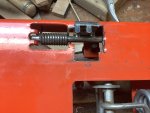
I removed the seat base on my GR2120 and I cannot figure out for the life of me how it can be reinstalled. Pictured is the rod in place, without the coil spring. The mechanical problem is that there is not enough clearance fore and aft, or up and down, to fit the L shaped “paddle” in the rectangular hole and slipping the end of the rod at the same time into its U shaped keeper. I have oriented the spring in the position I think it should go. Has anyone taken this thing apart and gotten it back together?
1696456761044.jpeg
 

Russell King

Well-known member
Lifetime Member

Equipment
L185F, Modern Ag Competitor 4’ shredder, Rhino tiller, rear dirt scoop
Jun 17, 2012
5,357
1,413
113
Austin, Texas
I know nothing about it but can ask a few questions about it and see if then I could help out.

What moves by the spring and what movements does the rod go through when moving the seat? The black round thing is a bumper or is it attached to the rod?

I assume the spring is torsional not a straight stretch type of movement.

Should the straight arm of the go down into the notch?

Did you ever take a picture of that area of the tractor in the past that might show it in position?
 

Maso

New member

Equipment
GR2120
Oct 4, 2023
13
0
1
Ashaway, Rhode Island
I know nothing about it but can ask a few questions about it and see if then I could help out.

What moves by the spring and what movements does the rod go through when moving the seat? The black round thing is a bumper or is it attached to the rod?

I assume the spring is torsional not a straight stretch type of movement.

Should the straight arm of the go down into the notch?

Did you ever take a picture of that area of the tractor in the past that might show it in position?
Your 4 questions might prompt others to chime in. Thank you.
1. Black disk is a bumper
2. In regular operation the perpendicular arm of the rod is under torsion spring pressure when turned down to adjust the back and forward motion of the seat. You sit there and move the lever from 2 o’clock to 4 as viewed from the rear. The two “fingers” evidently grip and release the rail on the slide; you move to the desired position while holding down the lever and then release to lock.
3. The fingered paddle welded to the rod fit down into the rectangular notch. there is about 1/16” clearance on either side of the paddle. Not much wiggle room.
4. Unfortunately no picture. My neighbor has an identical GR but the spring area is covered by a plate and is not visible. (I may ask him if I can loosen the plate and fender hold down bolts to take a look. Knowing the disposition still begs the question of how you thread the spring on the rod and the end of the rod through the keeper. My Kubota mechanic was mystified; he and his knowledgable boss were stumped when I presented the assembly. I did find a parts diagram that shows the spring in approximate position (labeled 60).
Any ideas?
1696507549882.png
 

RCW

Well-known member
Lifetime Member

Equipment
BX2360, FEL, MMM, BX2750D snowblower. 1953 Minneapolis Moline ZAU
Apr 28, 2013
9,134
5,192
113
Chenango County, NY
Was hoping parts diagram might help, but doesn't show much beyond rod going through spring.

Screenshot 2023-10-05 081942.jpg
 

Runs With Scissors

Well-known member

Equipment
L2501 TLB , Grappel, Brush Hog, Box Blade, Ballast box, Forks, Tiller, PH digger
Jan 25, 2023
2,417
2,782
113
Michigan
I know absolutey nothing about this....However it appears to me that the spring is bass'ackwards in your pic.

Is there a hole drilled in the rod near the end?

If so, I could imagine from your pic, that the "L" part of that spring faces to the right (in your pic) and goes in that hole, and then you give it "half a twist" to put tension on the spring as you feed the "straight" end (LH in pic) through a hole in the rod.

This in theory would "twist that rod" and keep those "fingers" in place

If there is no hole. I have no idea.
 

Maso

New member

Equipment
GR2120
Oct 4, 2023
13
0
1
Ashaway, Rhode Island
I know absolutey nothing about this....However it appears to me that the spring is bass'ackwards in your pic.

Is there a hole drilled in the rod near the end?

If so, I could imagine from your pic, that the "L" part of that spring faces to the right (in your pic) and goes in that hole, and then you give it "half a twist" to put tension on the spring as you feed the "straight" end (LH in pic) through a hole in the rod.

This in theory would "twist that rod" and keep those "fingers" in place

If there is no hole. I have no idea.
Good guess, but no hole in this 1/4” rod. If the orientation of the parts diagram is a clue, the L part of the spring bears against the finger flap, and the straight part bears on the side of the notch? Somehow that cocks the spring tension. The puzzle is how the spring is installed on the rod in order to line up with the U shaped piece I’ve been naming the keeper. I will see if a C-clamp can force the spring barrel down enough to push the rod home.
 

Russell King

Well-known member
Lifetime Member

Equipment
L185F, Modern Ag Competitor 4’ shredder, Rhino tiller, rear dirt scoop
Jun 17, 2012
5,357
1,413
113
Austin, Texas
It is somewhat difficult to visualize the movement and how the spring will have to be wrapped or unwrapped to make the movement return to the original position without the parts in hand.

I also assume that the spring is at the rear end of the shaft from the diagram.

So pushing down the rod handle will rotate the rod around in a clockwise direction from the rear end. That makes the fingered paddle move into a more horizontal position and should be unwrapping the spring (I think).

I would look for wear marks on the painted surface and see if they would indicate where the spring was rubbing the paint.

I also think that I see a hole in the paddle to rod joint but it couldc be just some missing weld.

What holds the seat in place when the rod is released? I think I recall seeing some method that used something like that toothed paddle into slotted holes in the sliding mechanism.
 

Maso

New member

Equipment
GR2120
Oct 4, 2023
13
0
1
Ashaway, Rhode Island
It is somewhat difficult to visualize the movement and how the spring will have to be wrapped or unwrapped to make the movement return to the original position without the parts in hand.

I also assume that the spring is at the rear end of the shaft from the diagram.

So pushing down the rod handle will rotate the rod around in a clockwise direction from the rear end. That makes the fingered paddle move into a more horizontal position and should be unwrapping the spring (I think).

I would look for wear marks on the painted surface and see if they would indicate where the spring was rubbing the paint.

I also think that I see a hole in the paddle to rod joint but it couldc be just some missing weld.

What holds the seat in place when the rod is released? I think I recall seeing some method that used something like that toothed paddle into slotted holes in the sliding mechanism.
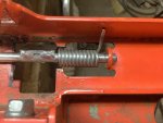
Thanks to your suggestions and some inference, I figured out why the assembly won’t go back together: at the factory, the spring was first installed on the rod and second, the paddle was welded to the rod. This explains the indented bits in my original photo. Instead of cutting the weld, I opted to cut a notch out of the base and also cut out the indents, which gave enough clearance to put the spring back on and ease the end of the rod through the keeper. I hope the pictures show the correct reassembly and the method of achieving it.
 

Attachments

cthomas

Well-known member
Lifetime Member

Equipment
LX2610 HSDC
Jan 1, 2017
865
579
93
La Farge Wi
I don't think that is right, the cogs have to be push towards the rail. Can you take pictures of any witness marks?
 

Maso

New member

Equipment
GR2120
Oct 4, 2023
13
0
1
Ashaway, Rhode Island
I’ll try to do that in the morning. THANKS!
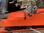
I noticed 11 marks corresponding to the 11 coils of the spring. You were correct that my attempt to cock the spring against the side of the frame was incorrect. Although I still needed to cut clearance notches or break the rod weld and re-weld it in the right position, I took another tack. Removed the seat slide base where the slides are bolted and saw a notch in the bottom rail where the fingers must fit. Here’s a picture with a stick pointing to the rail notch.
 

Attachments

Runs With Scissors

Well-known member

Equipment
L2501 TLB , Grappel, Brush Hog, Box Blade, Ballast box, Forks, Tiller, PH digger
Jan 25, 2023
2,417
2,782
113
Michigan
One thing I don't understand is: How did the spring came out in the first place?

It seems like your going through great lengths cutting/modifying, but didn't it just "fall out"?

My gut tells me there is a simpler solution.
 

Maso

New member

Equipment
GR2120
Oct 4, 2023
13
0
1
Ashaway, Rhode Island
One thing I don't understand is: How did the spring came out in the first place?

It seems like your going through great lengths cutting/modifying, but didn't it just "fall out"?

My gut tells me there is a simpler solution.
One thing I don't understand is: How did the spring came out in the first place?

It seems like your going through great lengths cutting/modifying, but didn't it just "fall out"?

My gut tells me there is a simpler solution.
I agree there should be an easier way to re-install the spring but the design makes it easier to pull out than to put back. The rod extends just 1/4” beyond the keeper, and it have been simple at the factory to drill a hole and fit a cotter pin, thus preventing the royal pain of re-installation.
I am responsible for the removal. When the engine unexplainable stopped, one culprit was the safety switch activated by the PTO lever. You can‘t get to that without removing the metal shell/fender. The shell can’t come off without removing the seat and its frame. I made the mistake of wrenching the lever to get the slide out and SPROING I heard the spring pop out of the keeper. Mind you, the end of the rod is covered by a dust or support plate, which is held in place by the two bolts that fasten the rear of the fender. If I had seen that rig, I would have been more careful taking out the seat slide.
The upshot is “don’t mess with the seat slide lever unless you have to…”
 

ve9aa

Well-known member

Equipment
TG1860, BX2380 -backblade, bx2830 snowblower, fel, weight box,pallet forks,etc
Apr 11, 2021
1,202
982
113
NB, Canada
I'm not there and don't know the answer, but I HIGHLY doubt that a spring was installed then something was welded when this was first made.

It just doesn't make good "assembly line" sense. (to my pea brain anyways)

I do wish you luck reinstalling. I also humbly suggest you're doing a bit too much cutting/grinding and possibly there is a better way....we just don't know the way yet.
 
  • Like
Reactions: 1 users