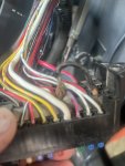
I have a M7040 with a cab and someone has put a jumper wire on the back of the fuse panel. The jumper the rear work likes hot wire for the fuse panel over to the AC compressor. The power was still running through the fuse but I do not see Kubota putting a jumper wire on the back of a fuse block. Does anyone know where the hot wire for the fuse panel that supplies the AC compressor fuse is suppose to come from?
M7040 AC wiring
- Thread starter Mikec575
- Start date
One diagram showing the fuse box is page 9-M3 from the WorkShop Manual. There are some model differences.
A diagram for the Air conditioning system is page 9-M17 from the WSM. That shows 3 different fuses for 3 subsystems of the air conditioning, such as controls, compressor, fan.
If you can better describe where the jumper is with regard to wire color coding, fuse identification, etc., maybe another M7040 owner can compare to their wiring.
One diagram showing the fuse box is page 9-M3 from the WorkShop Manual. There are some model differences.
A diagram for the Air conditioning system is page 9-M17 from the WSM. That shows 3 different fuses for 3 subsystems of the air conditioning, such as controls, compressor, fan.
If you can better describe where the jumper is with regard to wire color coding, fuse identification, etc., maybe another M7040 owner can compare to their wiring.
The jumper wire is on the back side of the fuse block from the hot side of the work light (rear) to the air con. (fan motor).
Attachments
-
388.1 KB Views: 138
Well, the picture helps, somewhat. The AC compressor, according to the diagram, should be fed from a 3.0 metric Red with White stripe conductor. The conductor comes a 6-pin connector attached to the main engine harness. The conductor occupies pin 4. On the mating connector the conductor goes to slow blow fuse box 2-3, from a 40A fuse. The conductor remains a 3.0 metric R/W.Does anyone know where the hot wire for the fuse panel that supplies the AC compressor fuse is suppose to come from?
One question is which is the hot conductor and which is the dud feeding the fuse box. I would suggest looking at that with an ammeter to see which one has current flowing.
On the left hand side of the diagram, looking at the fuse box, there are 5 feeders going into the fuse box supplying power. It is hard for me to see the stripes to see if all feeders are going to the fuse box.
Of course the other question is why the jumper to begin with. Did a conductor get damaged? Did a conductor pull out of its crimp, and not understanding how to release the crimp, a jumper was kludged in?
A matter of elimination by matching the physical wiring to the diagram and recording discrepancies.
Good luck.
This is for a friend, you know how's those jobs end up. He asked me to fix it for him. The orgional problem was with the fuel system. Found the sender unit to have rusted inside the tank glogging the lines.Well, the picture helps, somewhat. The AC compressor, according to the diagram, should be fed from a 3.0 metric Red with White stripe conductor. The conductor comes a 6-pin connector attached to the main engine harness. The conductor occupies pin 4. On the mating connector the conductor goes to slow blow fuse box 2-3, from a 40A fuse. The conductor remains a 3.0 metric R/W.
One question is which is the hot conductor and which is the dud feeding the fuse box. I would suggest looking at that with an ammeter to see which one has current flowing.
On the left hand side of the diagram, looking at the fuse box, there are 5 feeders going into the fuse box supplying power. It is hard for me to see the stripes to see if all feeders are going to the fuse box. So I have to find out why the red wire with white tracer doesn't have power.
Of course the other question is why the jumper to begin with. Did a conductor get damaged? Did a conductor pull out of its crimp, and not understanding how to release the crimp, a jumper was kludged in?
A matter of elimination by matching the physical wiring to the diagram and recording discrepancies.
Good luck.
He asked me to look at the Ac because it would blow intermittently andmentiomed the front work light no longer worked. Well that's the two circuits that were jumped and the jumper wire would vibrate and not make connection causing the Ac to work intermittently. The Red wire with the white stripe that's suppose to feed the power to the Ac portion of the fuse block does not have power. So they were robbing the power from work light feeder is what I have figured out this far.
Ktrim
Well-known member
Equipment
B2400, lA352 loader,3pth quick hitch/z122r zero turn/restored 52 farmall super a
My guess is somewhere along the line they had a compressor lock up, pull too many amps and take out the slow blow fuse that Jim l mentioned. I would search back to that and start there. At the very least run a new hot from a key on source, inline fuse it and properly splice into the original feed wire.This is for a friend, you know how's those jobs end up. He asked me to fix it for him. The orgional problem was with the fuel system. Found the sender unit to have rusted inside the tank glogging the lines.
He asked me to look at the Ac because it would blow intermittently andmentiomed the front work light no longer worked. Well that's the two circuits that were jumped and the jumper wire would vibrate and not make connection causing the Ac to work intermittently. The Red wire with the white stripe that's suppose to feed the power to the Ac portion of the fuse block does not have power. So they were robbing the power from work light feeder is what I have figured out this far.
My guess is somewhere along the line, they had a compressor lock up, pulled too many amps, and took out the slow blow fuse that Jim l mentioned. I would search back to that and start there. At the very least run a new hot from a key on source, inline fuse it and properly splice into the original feed wire.
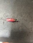
So I finally found the red with white tracer feeder wire broke inside the cabin harness plug in the floor.
So I tested everything before reassembling the head liner, top and the cover over all the controls. Everything worked great. After reassembly got ready to pull it out of the shop and now the AC blower motor isn't working, but I did not lose the power on that feeder wire. All the relays are clicking when turning the blower on off and the relay for the high fan is also working. Fuses in the fuse box are good and the slow blow fuses under the hood are good.
Was so close
Attachments
-
363.6 KB Views: 97
Ktrim
Well-known member
Equipment
B2400, lA352 loader,3pth quick hitch/z122r zero turn/restored 52 farmall super a
Broken. That burned off. Must have gotten nicked and went to ground.So I finally found the red with white tracer feeder wire broke inside the cabin harness plug in the floor.
So I tested everything before reassembling the head liner, top and the cover over all the controls. Everything worked great. After reassembly got ready to pull it out of the shop and now the AC blower motor isn't working, but I did not lose the power on that feeder wire. All the relays are clicking when turning the blower on off and the relay for the high fan is also working. Fuses in the fuse box are good and the slow blow fuses under the hood are good.
Was so close
Between that and the Jerry rigging that was done I would trace whole harness from the plug up into the cabin. Probably find another wire or few that got hot. Check for continuity on all wires going to fan.


