Kubota 7040 fuel solenoid problem

Steveroedd

New member

Equipment
2008 M 7040
Nov 6, 2022
9
0
1
Richards Landing ON
Hi,
I have a 2008 7040 tractor. It wouldn't start and I narrowed things down to the stop solenoid. I get 4.0 DC volts to both sides with the ignition switch turned on... but it wont engage. After removal the engine runs fine and can be shut off via the manual fuel shutoff on the injector (presumably the same one held open when the stop solenoid is not engaged).
When I jump the solenoid from my 12 v battery, one side (the start side) results in rapid cycling of the plunger... not a constant retraction, but the hold side does nothing. Is the 4.0 v sufficient or is the solenoid bad? Might the input voltage be too low? There is a 30 amp slow blow fuse running to the solenoid.
I'm not too mechanically or electrically inclined.. please keep things simple for me...
 

Dave_eng

Well-known member
Lifetime Member

Equipment
M7040, Nuffield 465
Oct 6, 2012
5,203
992
113
Williamstown Ontario Canada
You need to understand how to test the solenoid as you can easily damage it.
This is the test procedure.
forum M7040 stop solenoid test.jpg

There are two internal coils. Your haphazard testing may have already damaged the unit.
There is an internal switch which cuts power to the pull coil once the plunger moves.
forum m7040 stop solenoid internals.jpg

This is not a do it yourself project if your skills are weak as you can easily destroy expensive parts.

Dave
 
  • Like
Reactions: 2 users

Steveroedd

New member

Equipment
2008 M 7040
Nov 6, 2022
9
0
1
Richards Landing ON
Dave, thanks for your reply. Fair enough.
Indeed, my understanding is limited.

I have the shop manual, read this section and did not apply current for more than 2 seconds. I concur that I may have misunderstood the test procedure, because when they referred to “the switch”, I assumed this to be the starter switch in the tractor.

As I said,. I first removed the wiring harness from the solenoid and checked the voltage. Zero volts with key off... 4 volts on each side (2 positive wires P and H if I understood the description correctly, one start and one hold). I still do not know if this is the correct voltage to engage the solenoid, nor could I find this in the manual. I know this step was not part of the test procedure, but it seemed reasonable to see if any power was getting to the solenoid before doing anything else.

My second step was to have the solenoid still wired up to the tractor , but removed from the injector pump, (but grounded to it), so I could visually see what was happening . Turning the key started the tractor (which did not happen before removing stop solenoid), the stop solenoid did nothing. It seemed a reasonable conclusion that 4 volts, delivered to the grounded solenoid, via the tractor ignition switch did not cause it to work as the manual suggested it should. Am I missing something? If so, what?

I was still left with uncertainty because I did not, and still do not know, if this voltage is sufficient to cause the coils to engage as they should.

Scolding me does not really provide much assistance. I accept that my skills and knowledge are limited, but joined this site in good faith, to seek a community of people willing to help. I have exhausted all local assistance, and remain hesitant to float a tractor 50 km to the dealer to fix this.

Steve
 
Last edited:

Tx Jim

Well-known member
Lifetime Member

Equipment
M7040 HDC-1,JD 4255,Ford 6700
Apr 30, 2013
1,193
122
63
Coyote Flats,Texas
Welcome to OTT
I perceive Dave's post more as "warning than as a scolding".

Dave is very knowledgeable on your tractor's model due to he also owns a M7040

I hope I don't experience this same problem with my M7040
 
  • Like
Reactions: 1 users

Dave_eng

Well-known member
Lifetime Member

Equipment
M7040, Nuffield 465
Oct 6, 2012
5,203
992
113
Williamstown Ontario Canada
Dave, thanks for your reply. Fair enough.
Indeed, my understanding is limited.

I have the shop manual, read this section and did not apply current for more than 2 seconds. I concur that I may have misunderstood the test procedure, because when they referred to “the switch”, I assumed this to be the starter switch in the tractor.

As I said,. I first removed the wiring harness from the solenoid and checked the voltage. Zero volts with key off... 4 volts on each side (2 positive wires P and H if I understood the description correctly, one start and one hold). I still do not know if this is the correct voltage to engage the solenoid, nor could I find this in the manual. I know this step was not part of the test procedure, but it seemed reasonable to see if any power was getting to the solenoid before doing anything else.

My second step was to have the solenoid still wired up to the tractor , but removed from the injector pump, (but grounded to it), so I could visually see what was happening . Turning the key started the tractor (which did not happen before removing stop solenoid), the stop solenoid did nothing. It seemed a reasonable conclusion that 4 volts, delivered to the grounded solenoid, via the tractor ignition switch did not cause it to work as the manual suggested it should. Am I missing something? If so, what?

I was still left with uncertainty because I did not, and still do not know, if this voltage is sufficient to cause the coils to engage as they should.

Scolding me does not really provide much assistance. I accept that my skills and knowledge are limited, but joined this site in good faith, to seek a community of people willing to help. I have exhausted all local assistance, and remain hesitant to float a tractor 50 km to the dealer to fix this.

Steve
Steve
I am sorry if my reply seemed harsh. Never my intention and if that is how it felt at your end I am truly sorry. By way of an excuse for not being more cautious with my language, I was posting after 2 am because I could not sleep due to severe pain.

With many systems on today's tractors they do not tolerate a 'lets try it and see," approach and parts are destroyed in a fraction of a second. At 76 years of age, in my early years I had lots of parts go up in smoke or, if hydraulic crack. I had help from many and gradually learned.

Back to your situation.
There are a series of wiring diagrams for the different models of M7040 so posting your exact model will help ensure you and I am looking at the same wiring diagram
Any time you are seeing low voltages on a tractor without the latest electronic systems there is a problem. Usually rodent damage is the first to suspect as chewed wires can cause current paths to change resulting in low voltage at the end of a wire.

Although there are two wire terminals on the stop solenoid a short distance back in the wiring harness both join together.

forum M7040 S solenoid wiring.jpg

The fact that you are measuring 4 volts on both P & H just confirms they are joined.

The circuit path to the stop solenoid as far as the main power supply is concerned is simple and I have marked it in red.

forum M7040 S Solenoid logic.jpg

Locate the key stop relay #11 and with the key on measure the voltage going in to the relay and coming out of the relay. It should be 12 volts more or less and if it is not, then you need to work your way back to the slow blow fuse looking for damage or corrosion.

Dave
 
  • Like
Reactions: 2 users

Russell King

Well-known member

Equipment
L185F, Modern Ag Competitor 4’ shredder, Rhino tiller, rear dirt scoop
Jun 17, 2012
5,072
1,201
113
Austin, Texas
@Dave_eng now you have raised more questions on that circuit.

As a mechanical guy the circuit diagram symbols are somewhat difficult to remember what they mean so it may be obvious to a more electrically adept mind.

But as I understand the key stop solenoid operation the solenoid is only in operation to stop the motor for a few seconds so what is the point of the holding circuit? If it was a run solenoid I could understand the need for a holding coil to draw less power and to stay cooler over the time the tractor is in operation (running).

I guess the stop solenoid pulling coil is just not robust enough to hold for several seconds and survive probably due to economics of design?

Perhaps Kubota just uses the same solenoid in both situations and get a volume discount on it
 

Dave_eng

Well-known member
Lifetime Member

Equipment
M7040, Nuffield 465
Oct 6, 2012
5,203
992
113
Williamstown Ontario Canada
@Dave_eng now you have raised more questions on that circuit.

As a mechanical guy the circuit diagram symbols are somewhat difficult to remember what they mean so it may be obvious to a more electrically adept mind.

But as I understand the key stop solenoid operation the solenoid is only in operation to stop the motor for a few seconds so what is the point of the holding circuit? If it was a run solenoid I could understand the need for a holding coil to draw less power and to stay cooler over the time the tractor is in operation (running).

I guess the stop solenoid pulling coil is just not robust enough to hold for several seconds and survive probably due to economics of design?

Perhaps Kubota just uses the same solenoid in both situations and get a volume discount on it
Russell
The reason for the engine stop solenoid and how it is designed to work has two different strategies which creates the confusion.

I suspect but do not know that Kubota is getting engines, perhaps made under license or bought outright, from other manufacturers. This is why their stop solenoid operation is not consistent across their entire product line.

Strategy one: solenoid is powered throughout running engine operation. (hours or even days). This is where you see two coils within the solenoid assembly. A strong coil to have the strength to move the internal mechanism and a second weaker coil to hold the internals in the operating position once the strong coil has done its job.

Strategy two: Solenoid is powered to stop the engine. In the absence of power to the solenoid the engine will run until all fuel is used up. To stop the engine, the key switch is turned to OFF. You cannot have circuits continuing to constantly draw power when the key is OFF because the battery eventually will go dead. To overcome this constant drain, Kubota uses a form of timer to only allow the stop solenoid to be powered for seconds, just long enough for the engine to come to a dead stop. Sometimes the timer is in the Operator presence controller, sometimes it is an independent device. Kubota can use a solenoid designed for one strategy for the opposite one by the design of the wiring.

Your understanding of the operation described in your post outlines the second strategy in my explanation..

Someday there will be a chart showing which tractor model uses which engine stopping or running design.

Hope this helps!

Dave
 
  • Like
Reactions: 1 users

Dave_eng

Well-known member
Lifetime Member

Equipment
M7040, Nuffield 465
Oct 6, 2012
5,203
992
113
Williamstown Ontario Canada
Dave, thanks for your reply. Fair enough.
Indeed, my understanding is limited.

I have the shop manual, read this section and did not apply current for more than 2 seconds. I concur that I may have misunderstood the test procedure, because when they referred to “the switch”, I assumed this to be the starter switch in the tractor.

As I said,. I first removed the wiring harness from the solenoid and checked the voltage. Zero volts with key off... 4 volts on each side (2 positive wires P and H if I understood the description correctly, one start and one hold). I still do not know if this is the correct voltage to engage the solenoid, nor could I find this in the manual. I know this step was not part of the test procedure, but it seemed reasonable to see if any power was getting to the solenoid before doing anything else.

My second step was to have the solenoid still wired up to the tractor , but removed from the injector pump, (but grounded to it), so I could visually see what was happening . Turning the key started the tractor (which did not happen before removing stop solenoid), the stop solenoid did nothing. It seemed a reasonable conclusion that 4 volts, delivered to the grounded solenoid, via the tractor ignition switch did not cause it to work as the manual suggested it should. Am I missing something? If so, what?

I was still left with uncertainty because I did not, and still do not know, if this voltage is sufficient to cause the coils to engage as they should.

Scolding me does not really provide much assistance. I accept that my skills and knowledge are limited, but joined this site in good faith, to seek a community of people willing to help. I have exhausted all local assistance, and remain hesitant to float a tractor 50 km to the dealer to fix this.

Steve
Steve
When you are measuring 4 volts you have removed the wiring connector from the solenoid.
One probe is against the terminals inside the connector. Where are you grounding the other multi meter lead? It should be against the metal of the engine i.e. a battery ground.
it should NOT be against the terminals of the stop solenoid or you will read low voltages because your reading is in series with the internal coils.
Dave
 
  • Like
Reactions: 1 users

Steveroedd

New member

Equipment
2008 M 7040
Nov 6, 2022
9
0
1
Richards Landing ON
Steve
I am sorry if my reply seemed harsh. Never my intention and if that is how it felt at your end I am truly
Steve
When you are measuring 4 volts you have removed the wiring connector from the solenoid.
One probe is against the terminals inside the connector. Where are you grounding the other multi meter lead? It should be against the metal of the engine i.e. a battery ground.
it should NOT be against the terminals of the stop solenoid or you will read low voltages because your reading is in series with the internal coils.
Dave
Hi again Dave. Cold and raining... so haven’t been out to review the electronics and find the physical relays. I grounded to the engine rather than the battery. I appreciate the basic things you question... because I know so little... I could easily provide inaccurate info.
Today is just cold.. so will try to move forward. I did note that some lights seem not to be working when I went out briefly in the downpour.
 

Steveroedd

New member

Equipment
2008 M 7040
Nov 6, 2022
9
0
1
Richards Landing ON
Steve
When you are measuring 4 volts you have removed the wiring connector from the solenoid.
One probe is against the terminals inside the connector. Where are you grounding the other multi meter lead? It should be against the metal of the engine i.e. a battery ground.
it should NOT be against the terminals of the stop solenoid or you will read low voltages because your reading is in series with the internal coils.
Dave
Somehow My replies don't seem go through... Thanks for this Dave. Yes, I grounded to the engine not the battery. It was pouring rain yesterday... today just cold... I'll try to find the various relays and move forward on your helpful testing suggestions once it warms up. Steve
 

Steveroedd

New member

Equipment
2008 M 7040
Nov 6, 2022
9
0
1
Richards Landing ON
Steve
I am sorry if my reply seemed harsh. Never my intention and if that is how it felt at your end I am truly sorry. By way of an excuse for not being more cautious with my language, I was posting after 2 am because I could not sleep due to severe pain.

With many systems on today's tractors they do not tolerate a 'lets try it and see," approach and parts are destroyed in a fraction of a second. At 76 years of age, in my early years I had lots of parts go up in smoke or, if hydraulic crack. I had help from many and gradually learned.

Back to your situation.
There are a series of wiring diagrams for the different models of M7040 so posting your exact model will help ensure you and I am looking at the same wiring diagram
Any time you are seeing low voltages on a tractor without the latest electronic systems there is a problem. Usually rodent damage is the first to suspect as chewed wires can cause current paths to change resulting in low voltage at the end of a wire.

Although there are two wire terminals on the stop solenoid a short distance back in the wiring harness both join together.

View attachment 90143
The fact that you are measuring 4 volts on both P & H just confirms they are joined.

The circuit path to the stop solenoid as far as the main power supply is concerned is simple and I have marked it in red.

View attachment 90144
Locate the key stop relay #11 and with the key on measure the voltage going in to the relay and coming out of the relay. It should be 12 volts more or less and if it is not, then you need to work your way back to the slow blow fuse looking for damage or corrosion.

Dave
Hi Dave. I had replied to this... but somehow it did not go through. First, I'm grateful for your help. Second, even more grateful that you reflected on my perceptions about tone. Third... my response may have also been impacted by time I read them (also in the middle of the night, but due to a needed but problematic drug (high dose prednisone). It's so hard to sort out nuance of things in text, and my sensitivity is likely part of the equation. Anyway...

I will try and get to this once it warms up... I'll get the specific model and post it... I'm not sure where the relays are physically...and my manual isn't totally clear.. But I'll try to find everything and report back. Steve
 

Steveroedd

New member

Equipment
2008 M 7040
Nov 6, 2022
9
0
1
Richards Landing ON
Welcome to OTT
I perceive Dave's post more as "warning than as a scolding".

Dave is very knowledgeable on your tractor's model due to he also owns a M7040

I hope I don't experience this same problem with my M7040
Thanks Jim... I concur... its hard to sort out intent... when things go through my filters as well. Nice to have an objective observer. I always try to keep things clear... so that I am less likely to "react"...
Its Clear that Dave knows a TON... with 78 years of experience... and is a kindred spirit... in that neither of us sleep much.
 

Dave_eng

Well-known member
Lifetime Member

Equipment
M7040, Nuffield 465
Oct 6, 2012
5,203
992
113
Williamstown Ontario Canada
Thanks Jim... I concur... its hard to sort out intent... when things go through my filters as well. Nice to have an objective observer. I always try to keep things clear... so that I am less likely to "react"...
Its Clear that Dave knows a TON... with 78 years of experience... and is a kindred spirit... in that neither of us sleep much.
Steve
Please advise on your specific model of M7040. I have not seen it if you already have.
The slow blow fuses are in a removable panel below the gear shift lever.
A nice place for nesting rodents.
forum M7040 slow blow fuse location.jpg

I will try and determine which fuse is involved but so far it is not obvious in the Operators' manual.
I am hoping you will remove the panel and see rodent damage immediately.
I leave my panel off because the cables for the remove hydraulic valves freeze up and the warming cab once the engine is going for a while free them up.
Dave
 

Steveroedd

New member

Equipment
2008 M 7040
Nov 6, 2022
9
0
1
Richards Landing ON
Steve
Please advise on your specific model of M7040. I have not seen it if you already have.
The slow blow fuses are in a removable panel below the gear shift lever.
A nice place for nesting rodents.

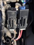
Hi Dave. My Tractor model is DTHSC. I think my layout must be different. I took photos of what is under the gear lever. 2 x 20 Amp fuses and 2 relays... (not sure what they go to)... removed so you can see them. No rodent damage..

I think my slow blow fuses and relays are in the engine compartment, behind and above the rad. See photos.

I have two relays, and two sets of slow blow fuses... I don't see any rodent damage there either.. I have that panel open as well... for the same reason!
The smallest image is the two large relays. I believe the one on the left is the key stop relay, because the engine will not start with it removed, but will if the one on the right is removed. . Input voltage = battery voltage with the key on.
I am guessing (from my manual), that the one on the right is the "Glow " relay).. It's been working fine.

Please pardon my ignorance, but how to I test output voltage on the relays? I swapped relays (they are identical) and the tractor starts with both.

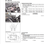
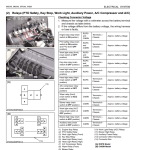
The last 2 images are what my manual shows for relays... But I have no idea where they may be!
314921162_557404319723649_8428475113094770808_n.jpg
314378777_661642495372354_3677398832899253578_n.jpg
315027223_503692875112797_6684961524627861230_n.jpg
 

Attachments

Last edited:

Dave_eng

Well-known member
Lifetime Member

Equipment
M7040, Nuffield 465
Oct 6, 2012
5,203
992
113
Williamstown Ontario Canada
Can anyone tell me where the bank of relay's are... physically... on the tractor ? View attachment 90392
Steve
This is a quick and dirty answer from the top of my head.

The seat sits on a metal box. On the front face of his box (which is facing the pedals) is a metal panel held on by 4 bolts. Remove that panel and I think you will find electrical stuff inside.

Not certain if this will be the relays you are looking for but until I have time to do more research this is my best advice.

Dave
 
  • Like
Reactions: 1 user

Steveroedd

New member

Equipment
2008 M 7040
Nov 6, 2022
9
0
1
Richards Landing ON
Steve
This is a quick and dirty answer from the top of my head.

The seat sits on a metal box. On the front face of his box (which is facing the pedals) is a metal panel held on by 4 bolts. Remove that panel and I think you will find electrical stuff inside.

Not certain if this will be the relays you are looking for but until I have time to do more research this is my best advice.

Dave
Thanks Again Dave... Thats where I will look in the morning... but... first day of deer season... so a late start...
 

TexasKen

New member

Equipment
M7040 hydro, L3400 hst
Oct 17, 2017
1
0
1
North Zulch, Texas, USA
The easiest way for the layman, (ME), to trouble shoot this solenoid is;
With the KEY switch OFF!
First, check the 30A fuse! If blown, something caused it to blow, BAD SOLENOID COIL or RATS chewing the wires
Second, check continuity across both terminals, ONE AT TIME, unplug the solenoid, touch one probe to the housing and one to a solenoid terminal, both should show continuity, if not, get yourself a new stop solenoid, if you can't reach it, remove it then check it,
Mine was clicking when I turned the key on until it smoked and blew the fuse. I believe ONE of the internal coils in the STOP SOLENOID had gone to ground.
If you replace the solenoid, be sure you guide it into position before you tighten it, it can be installed off center and you will RUIN STUFF!

Good luck