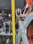
Lift Arm Adjustment

gorsuchmill

New member

Equipment
L2501
Feb 18, 2022
12
1
3
Upperco, MD
I have an older B7500 that I bought used. It had been worked pretty hard before I acquired it. Anyway, the 3PH has never raised as high as I would expect. For example, I have a 4' Bush Hog that when adjusted for level at the bottom only raises about 8" off the ground when the lift harms are raised fully. I realize I can get more lift by adjusting the top link, but doing so changes how the hog is positioned at ground level.

I looked to see if the feedback rod needed adjustment and I think I've got that sorted just fine. However, I note there appears to be lots more downward travel available (at least 8" below ground level), which has me wondering if I'm simply not getting as much rotation out of the lift harms as is available. That is, the arms are currently oriented to go lower than they need to but not as high as they should. Is it reasonable to think I could remove the lift arms, rotate them, then reattach them in a way to have more upward rotation and less downward?

Thanks much.
 

Pawnee

Well-known member

Equipment
L2501
Jul 1, 2021
351
306
63
Ontario Canada
is there more than one hole in the lift arms for the lifting rods?
My L2501 has 2 positions, 1 for more height, one for more weight.
 

GreensvilleJay

Well-known member

Equipment
BX23-S,57 A-C D-14,58 A-C D-14, 57 A-C D-14,tiller,cults,Millcreek 25G spreader,
Apr 2, 2019
11,421
4,908
113
Greensville,Ontario,Canada
had a quillook. if this is your 3pt, then there are other holes ,also, it may be possible the arms are 'backwards', Implement end on tractor, and vice versa ??
 

Attachments

gorsuchmill

New member

Equipment
L2501
Feb 18, 2022
12
1
3
Upperco, MD
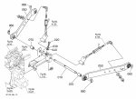
Thanks for the feedback. Maybe I have it wrong but I believe you're referring to the link arms. The lift harms, or at least as I understand it, are on both sides of the top link and actually do the lifting when the 3PH is engaged.

Capture.PNG
 

Dieseldonato

Well-known member

Equipment
B7510 hydro, yanmar ym146, cub cadet 1450, 582,782
Mar 15, 2022
728
439
63
Pa
Thanks for the feedback. Maybe I have it wrong but I believe you're referring to the link arms. The lift harms, or at least as I understand it, are on both sides of the top link and actually do the lifting when the 3PH is engaged.

View attachment 82577
There are dots on the shaft and arms for alignment of the arms to the rock shaft. You may have to pull the snap rings off the ends to see if they are lined up. The arms on my B7510 drop down to about an inch or two off the ground and raise up to just over the halfway point of the rear tires. (Sorry going off memory, I'll try to get some pics and measurements tomorrow)
The feedback rod basically limits upper and lower travel of the arms, within design limits. Hence the spring on the up position is so you can't send the internal piston crashing into the case. Last time I made any adjustments it was a but tedious to get the upper limit set right with the spring compressing at the right time to kick the control lever back to neutral. Lower lever was/is pretty easy.
 
  • Like
Reactions: 1 user

gorsuchmill

New member

Equipment
L2501
Feb 18, 2022
12
1
3
Upperco, MD
There are dots on the shaft and arms for alignment of the arms to the rock shaft. You may have to pull the snap rings off the ends to see if they are lined up. The arms on my B7510 drop down to about an inch or two off the ground and raise up to just over the halfway point of the rear tires. (Sorry going off memory, I'll try to get some pics and measurements tomorrow)
The feedback rod basically limits upper and lower travel of the arms, within design limits. Hence the spring on the up position is so you can't send the internal piston crashing into the case. Last time I made any adjustments it was a but tedious to get the upper limit set right with the spring compressing at the right time to kick the control lever back to neutral. Lower lever was/is pretty easy.

Thank you.
 

GreensvilleJay

Well-known member

Equipment
BX23-S,57 A-C D-14,58 A-C D-14, 57 A-C D-14,tiller,cults,Millcreek 25G spreader,
Apr 2, 2019
11,421
4,908
113
Greensville,Ontario,Canada
It's unlikely you'll have to remove/adjust/replace the 'lift arms' ( upper ones - in red circle ). After about a month they'd be dang near impossible to easily remove,over time it gets even harder(BTDT).
Unless the unit was repaired, no need for the arms to have ever been off.
Then again, someone in the past may have done just that, to mate with their implement better ?
 

Dieseldonato

Well-known member

Equipment
B7510 hydro, yanmar ym146, cub cadet 1450, 582,782
Mar 15, 2022
728
439
63
Pa
It's unlikely you'll have to remove/adjust/replace the 'lift arms' ( upper ones - in red circle ). After about a month they'd be dang near impossible to easily remove,over time it gets even harder(BTDT).
Unless the unit was repaired, no need for the arms to have ever been off.
Then again, someone in the past may have done just that, to mate with their implement better ?
Doesn't hurt to pop 2 snap rings off and verify, it's not like he had it since new.
 

gorsuchmill

New member

Equipment
L2501
Feb 18, 2022
12
1
3
Upperco, MD
Doesn't hurt to pop 2 snap rings off and verify, it's not like he had it since new.
Thanks for the feedback. I actually had to replace one of the arms a couple of years ago when the splines wore out and tried to match it with the orientation of the other. I don't know whether the one I didn't replace was original or not. Regardless, it seemed to me that if the rotational travel allowed an implement to go lower than necessary then rotating the arms back slightly might improve the height without negatively impacting the bottom end. If it's not a dumb idea I might give it a try. As a reference, does anyone have a picture of those arms in a fully raised position? If so, then it would at least answer whether that could be the culprit.

As always, I appreciate you help.
 

Dieseldonato

Well-known member

Equipment
B7510 hydro, yanmar ym146, cub cadet 1450, 582,782
Mar 15, 2022
728
439
63
Pa
I'm at work now, won't get home till around 9:30 tonight if I'm lucky. I'll take some pictures and measurements if it's still light out, or in the morning before I leave for work again.
 
  • Like
Reactions: 1 user

gorsuchmill

New member

Equipment
L2501
Feb 18, 2022
12
1
3
Upperco, MD
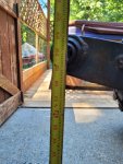
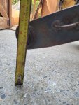
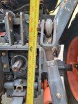
Here's a few pictures for you. Took them at the lift arms and the drag arms.
These are very helpful, thank you!! So, looks like about 7" total lift (26" to 33") for the link arms (top pieces) from the high setting to low. I'll see if I'm getting the same and report back.
 
  • Like
Reactions: 1 user

Rusty46

Member

Equipment
B7500 HSD-R, LA 302, RCK60-24B, Woods RB-72, Millcreek 25, Harrow, Payne PF800,
I just measured my 2003 B7500. The centerline of the ball swivels measure 8-1/4" from grade at the lowest, and 25-3/4" at the highest. My current lift is 17-1/2". I bought the tractor new and have never adjusted the lift arms. My MMM is currently mounted on the tractor. I don't know if that affects either measurement. Note, I do have the Pat's system installed, but my measurements are at the point were an implement would attach if the Pat's was not there.
 
  • Like
Reactions: 1 users

gorsuchmill

New member

Equipment
L2501
Feb 18, 2022
12
1
3
Upperco, MD
I just measured my 2003 B7500. The centerline of the ball swivels measure 8-1/4" from grade at the lowest, and 25-3/4" at the highest. My current lift is 17-1/2". I bought the tractor new and have never adjusted the lift arms. My MMM is currently mounted on the tractor. I don't know if that affects either measurement. Note, I do have the Pat's system installed, but my measurements are at the point were an implement would attach if the Pat's was not there.

I was able to measure the link arm at the ball end in the fully raised position and it's right at 33", which matches what DieselD has measured. So, I think it's probably ok. Fully raised my Bush Hog is only 9" off the ground using the lower top link hole. If I move the top link to the upper hole it's only 7" off the ground. Both seem pretty low to me, but perhaps it is what it is. Thanks everyone for the feedback and help!
 

Dieseldonato

Well-known member

Equipment
B7510 hydro, yanmar ym146, cub cadet 1450, 582,782
Mar 15, 2022
728
439
63
Pa
I believe the lower hole is considered the standard hole. Can't say I've ever felt the extra twist from the top hole was needed... ymmv
 

Russell King

Well-known member
Lifetime Member

Equipment
L185F, Modern Ag Competitor 4’ shredder, Rhino tiller, rear dirt scoop
Jun 17, 2012
5,368
1,415
113
Austin, Texas
Which end of the mower are you talking about only raising about 8 inches?

The top link only effects the rear lift so leave it off and see if it lifts higher at the front end. I don’t think that it will make much difference at the front end.

The mower three point hitch is generally fairly high on the mower and the front end is supposed to be higher than the rear to help eject the mown grass out of the rear.. How high can the rear of the mower go and still be running on the rear wheel?
 
Last edited:

RalphVa

Well-known member
Jan 19, 2020
738
320
63
Charlottesville
Check the length of your top link vs. lower lift arms. Could be that your top link is longer than lower lift arms. I had this on my JD 4010 (like a 2019E if made). They'd put the lift pins on the brush hog in the wrong position.

If the top link it too long, it will drive the trail wheel down as you lift the front. Trail wheel will lift some, but not much.

Look for other holes on your brush hog to affix the lift pins to.