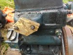
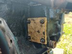
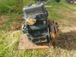
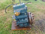
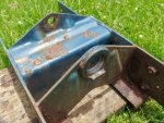
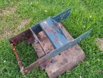
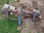
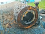
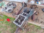
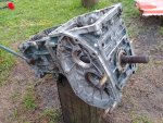
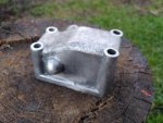
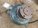
Kubota B6000 Restoration

flangefrog

Member

Equipment
Kubota B6000
Nov 29, 2021
38
5
8
31
Auckland, New Zealand
Continued...

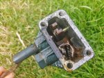
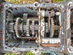
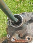
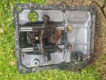
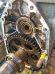
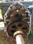
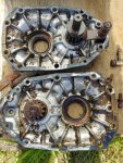
I took the gear case cover off. Mostly to help me get the oil seal out but also to inspect inside and reseal it. It had been taken off before and the original broken gasket was combined with gasket maker. I removed the remains of the original gasket and reattached the cover with gasket sealer only. Everything looked very good except for the lowest gear which I could very slightly wobble. I forgot to inspect that further though.
20211207_200929_HDR.jpg
 
Last edited:

Nicksacco

Well-known member

Equipment
Kubota L35 TLB, 2014 RTV-1140CPX
Sep 15, 2021
686
395
63
Bahama, NC
Ah, that makes sense about the way you posted - I hadn't thought about that.

Wow - you're really getting to the good stuff.
Yes, I thought that the hydro and engine oil would be really bad but it doesn't sound like you have any internal damage. I hope not.

So I didn't even realize that was a thermosiphon system. In that case having the original radiator is a good thing. It also makes sense it is a double row - lots of capacity. Perhaps in future you can fit a water pump but not something to go after now eh? The build up inside is probably from lack of maintenance and old age. The idea of running a cleaner through it is good.
I found some other threads you may find interesting and/or helpful:


Do you have a pressure washer? Looking at the crud on the engine makes me want to join you for that job!
All in all, I've already said you've got great focus getting this thing into shape. Hopefully there won't be any internal issues requiring large cash outlays.

Orings and gaskets are easy. You probably already know that gaskets are also used to provide the correct spacing and such. I know you have the shop manual for this engine/tractor. Those usually have runout and other tolerances listed.

I went back to your original pics and yes, the beast has come a very long way! Is the dashboard salvageable? It looked pretty rough but still fixable with some work.

Have you got a mental idea of your target dates for engine start and completion? Are you having issues securing parts or supplies? The before and after of the machine will be dramatic. Get lots of pics and share with Kubota headquarters.

Awesome project!
 

flangefrog

Member

Equipment
Kubota B6000
Nov 29, 2021
38
5
8
31
Auckland, New Zealand
I think most of the water in the oil was probably only from the last couple of years. The tractor never had any issues with the transmission while I was using it.

Thanks for those links. I had been thinking about whether a water pump would be a good idea. I'd like to put a water and engine temp sensor on it sometime.

I do have a pressure washer, but I wasn't sure if getting water in the manifold or air intake would be a bad idea? I don't think the engine should be that hard to clean actually. I bought some CRC Hot Shot engine degreaser, Exoff cleaner and a nice little scrubbing brush.

Proper pre-cut gaskets are too expensive to buy at the moment and I'm not sure how easy they'd be to cut from a sheet without a laser cutter? I've been keeping the spacing in mind, but it doesn't seem like it's too important on anything I've worked on so far. Although the engine front gear case will be sitting slightly closer so the max engine rpm adjuster may be at a bit lower RPMs than it was before and might need to be adjusted. And I wonder if closer spacing will cause increased corrosion on some parts.

I'd like to get the tractor mostly back together by christmas. I do have a lot of focus but I can lose that very easily if things drag out or stop being enjoyable. There's a couple of things holding me up at the moment - the blue paint and the need to weld some things. Painting is not really my thing. There's a rumour my dad may be buying me a mig welder for christmas (he wants it too). So that would be helpful. But there may be an arc welder here I could use, I haven't looked yet.

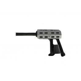
So hopefully the tractor will be running shortly after christmas, but the completion will take a bit longer and may be dependant on funds. There's a lot of panel work to be done. The engine cover and lights frame are heavily damaged. One of the rear mud guards is mostly complete but the other has mostly rusted away. The dashboard is fine though. I need to sort out a muffler too. There's a muffler at Tracpartz that's not too expensive and with a good shipping price:
Or maybe I could build or adapt one.

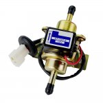
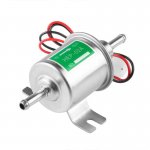
I did some research about the fuel lift pump on this tractor. It seems that it's a low pressure solenoid pump that is very common on many different vehicles and can be run with zero flow without damaging it. There's some info at the following links:
The first link shows a mechanical circuit to provide the pulses to the solenoid. But the pump on the kubota is solid state like the ones in the second link and the little plastic box on top is the control circuit. I remember now that when I looked at the pump last year I found the electronics were faulty but I couldn't get into them as they were potted in epoxy. So the relay circuit I made to provide pulses was doing pretty much what the original solid state electronics were but with an annoying buzzing sound and probably not great reliability. I could create a new solid state circuit but it would be a bit of time and effort and not worth it.

There are a lot of generic fuel lift pumps available on eBay and Aliexpress for very low prices. There are a couple of common models. EP-500-0 looks very similar to the original pump with that extra box for the electronics. There is also the HEP-02A which is a bit cheaper and has the electronics integrated in the main cylinder (I bet they're way smaller than was possible at a good price when the B6000 was made). There are sellers on our local auction site Trade Me selling both models at good prices. I bought the HEP-02A for $13.90.
1506370995.jpg 1638322914.jpg

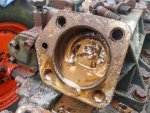
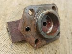
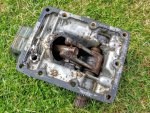
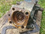
Yesterday I removed the piston cover/aux hydraulics connector. There was a lot of gunk inside. The small o-ring on the hydraulic inlet on the cap is about 7mm ID x 11mm OD x 2mm thick.
20211208_134159_HDR.jpg 20211208_134217_HDR.jpg

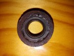
I also removed the cover and oil seal from the rear PTO. The oil seal is 25x38x7mm.

I went to Waitemata Hydraulics and Bearing supplies, Repco and Mitre 10. Waitemata Hydraulics supplied me all the o-rings and bolts I needed. I also got some hammerite blue paint to try. I was going to buy some castle nuts for the rod ends/heim joints on the steering but they were $32 each (!) so I left it for now. Maybe I'll obtain them on eBay. I also bought some new hydraulic plugs to replace the rusted ones.

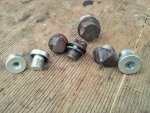
The new small plugs for the rear wheels are part B04INT 1/4" BSPPM captive seal plug. for $11.17 each. The middle size plug that goes opposite the bottom hydraulic hard line under the chassis is 3/8" and is $15.08. I didn't end up getting the large plug which is for the aux hydraulics near the piston as it was $22 and the old one is still usable. The seals in the new plugs are a bit different. instead of a steel washer with a rubber seal on the inside, they have a groove in the head and a flat rubber washer that fits inside.
20211208_205239.jpg

At Bearing Supplies I got some more oil seals and a new bearing for the tensioner pulley. It was stock code C6203-2RS, ID 17mm, OD 40mm, width 12mm. I'm not sure if this is the original type. There were some shim washers stuck inside that were bent into a cone as well so it looks like this was replaced before.

I got some paint at Mitre 10 to try as well as some circlip pliers I sorely needed. Repco had all the solvent and cleaner consumables at a good price.

Today I went to Bunnings for a bit more paint.

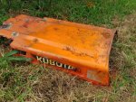
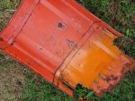
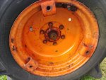
Here are some of the results of testing the paint I bought. The Rust-Oleum real orange is quite a bit more yellow than the redder orange on the engine cover. However I think the orange colour on this tractor has been repainted, possibly with the new kubota orange colour instead of old. The older colour beneath seemed more similar to the one I bought.
20211209_165021_HDR.jpg 20211209_165029_HDR.jpg

On the rear wheel almost all of the most recent coat of paint has flaked off. The paint I bought is actually a pretty good match for what I'm assuming is the original orange paint, just not so faded.
20211209_165047_HDR.jpg

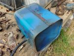
None of the blues were a good match. Top on the fuel tank with the brush strokes is Hammerite smooth blue. Dark blue is Plastikote pacific blue. the lighter blue on the right is Plastikote mediterranean blue. And the teal on the left is Rust-Oleum deep teal. I'm pretty sure the blue paint on this tractor is original. There are some kubota matched spray cans available at a few places here. But all about $40. I might just have to bite the bullet and go for one of those. Probably would have been cheaper than buying lots of low cost cans. But maybe I'll do a primer and first coat with different colour for now.
20211209_165054_HDR.jpg 20211209_165424_HDR.jpg
 
Last edited:

flangefrog

Member

Equipment
Kubota B6000
Nov 29, 2021
38
5
8
31
Auckland, New Zealand
Continued...

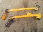
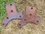
Here are the brake arms with Wattyl Killrust sungold yellow on the top and White Knight rust guard golden yellow on the bottom. Both are a bit more yellower than the original colour that was more orange. But they will do for now and can be overpainted later. The bottom one looked better and more glossy.
20211209_204920.jpg

I removed the hydraulic lever. I'd recommend not pushing the lever too far - the ball bearing and spring will pop out as seen in the photo.
20211209_165653_HDR.jpg

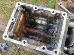
I then removed the diff and transmission covers. The gears look like they're in very good condition. But there's a lot of gunk and a bit of rust in the diff. I think this is because the oil is mostly circulating in the transmission and the oil in the diff is a bit more stagnant. I think that when I'm ready to put the covers on, I might water blast it, put some evapo-rust in, rinse out with water, use a water displacement spray and then immediately fill it with oil.
20211209_164822_HDR.jpg 20211209_164829_HDR.jpg

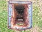
Here is the gear shifter. The rubber boot was there but was damaged so that might be how some of the water got in. Not sure if it will be easy to find a generic replacement in the right size.
20211209_181841_HDR.jpg 20211209_181830_HDR.jpg

This is the hydraulic piston for the lift arms.
20211209_164912_HDR.jpg 20211209_165254_HDR.jpg

That "extra lever" actually does move a gear back and forth on the PTO shaft. But it seems to be unable to lock into a different position as the gear rubs on something. I can't see what it does as it's at the very bottom and I don't want to disassemble the trans any further. Maybe it's not supposed to move. But then why add all the internal actuator components and gear? Both the parts book and the service manual are too low resolution to see anything.
20211209_165107_HDR.jpg

I haven't posted this pic yet, it is the brackets (non-original?) for the three point hitch.
20211209_165751_HDR.jpg
 
Last edited:

flangefrog

Member

Equipment
Kubota B6000
Nov 29, 2021
38
5
8
31
Auckland, New Zealand
Continued...

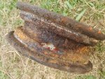
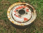
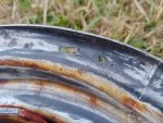
I removed the remains of the damaged tyre from the front rim and wire brushed it. There was actually more rust than I thought. There is a big hole on the inside and more smaller holes that showed up when the rust was brushed off. I know I can fix this but it will be a bit of work. The rim probably won't ever be as strong as it was originally but it probably won't ever be under too much stress.
20211209_180019_HDR.jpg 20211209_180030_HDR.jpg 20211209_201301_HDR.jpg

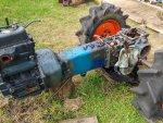
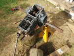
I removed the engine from the bell housing. I then removed the bell housing and main chassis from the transmission.
20211209_201753_HDR.jpg

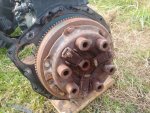
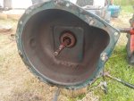
The clutch and bell housing look fairly good. A bit of surface rust. There was a tiny bit of play on the bearing that presses the clutch but I think it's not worth replacing. I wonder whether it would be ok to submerge the whole clutch assembly (if I can take it off) in Evapo-rust?
20211209_195025_HDR.jpg 20211209_195012_HDR.jpg

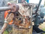
There's a bit of corrosion on the transmission and several seals that need replacing. Interesting that there's a PTO shaft here that can be connected to. Maybe for a centre mower deck? But not sure how it would go through the chassis.
20211209_201104_HDR.jpg

The chassis is quite rusty inside. I think it may be missing covers for the access holes? Edit: no, one of the holes is for the front wheel drive. Maybe the other is for a mower? I think there were bolt holes for a cover around at least one of the holes.
20211209_201140_HDR.jpg

There's a seal on the front wheel drive shaft cover that needs replacing.
20211209_201201_HDR.jpg
 
Last edited:

flangefrog

Member

Equipment
Kubota B6000
Nov 29, 2021
38
5
8
31
Auckland, New Zealand
Continued...

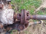
The main drive shaft has this attachment with a rubber washer in between. There was a whole lot of play. Not sure if it's supposed to be like this? I'm guessing probably not. Haven't read the service manual yet to see if it's mentioned.
20211209_201233_HDR.jpg
 
Last edited:

Nicksacco

Well-known member

Equipment
Kubota L35 TLB, 2014 RTV-1140CPX
Sep 15, 2021
686
395
63
Bahama, NC
Amazing work and dedication!
Let's see where do I start?

A pressure washer can be used, but yes, you will have to exercise care around intake and exhaust areas. If you use it, you can either stay away from those areas or plug them up. When my tractor was apart, I used a gas blower to dry it off on the outside and then removed the plastic bags I stuffed in the ports.
Your idea is excellent as well and hot water will go a long way too.

Gasket material isn't too hard to cut especially if you use an xacto knife or similar and cut on a smooth hard surface. I liked to use a piece of glass. Expect to have plenty of extra blades available too.
Not sure what you mean about the corrosion due to closer spacing of parts. Unless I am misunderstanding - paint would help that. Some parts that don't have critical spacing might just require some silicone sealant - RTV.

I ended up buying the Kubota blue-ish spray paint for the engine and NEW Kubota BRIGHT Orange for the tractor. For the frame, I used Rustoleum smoke grey and for some parts, I used my Squirrel grey powdercoating. I wasn't trying to concern myself with a historical reproduction however.

That is a good price on the muffler. The OEM muffler for mine was over $500 but I found a nearly exact replacement for about $150 by reviewing other Kubota mufflers with similar style on the D1703 engine and other tractors.

I think you'll be fine with the lift pump you chose. Least of the worries right now anyway.

That's a good score for Orings and such. I know the castle nuts are crazy priced. I had to replace both tierods on my L35 - they and the nuts were way overpriced. But I had no choice - nothing else would fit and work properly. That's just how it goes.

You're correct - Kubota does make two oranges - check out the attached.
Also with regard to the brake arms, if you wanted the arms to be smooth again, that would be an excellent use of the Bondo we'd discussed. There's no strength required and you could sand the rods and paint them so they looked new.

The rust on the gear boxes isn't bad really. You could indeed fill the cavities with evaporust, however the evaporust like other rust converting chemicals turn the rust to a carbon. The carbon should be removed else you will have carbon grit in the transmission. If you ignore the rust, and fill with oil, then the rust will eventually get loose and we're back to grit in the transmission. Perhaps a suggestion is to see just how much rust you can remove using a manual method (like drill and wire brush). But then the bearings could get the rust inside them. I don't know what do you think? Am I making too much of it?

As for submerging the clutch - here's the thing - evaporust leaves a residue that prevents flash rusting. That might cause the clutch to slip. Maybe only submerge the flywheel side and use a wire brush on the other (Fiber) side. Or not submerge the fiber.

The extra lever. Hmmmm, now that you can see the gears do you think it is a high/low range thing? Could it be a fast and slow PTO speed? Could it be a PTO reverser? Could that control the mower PTO? You're right, I can't make anything out from the terrible resolution of the manual either.

Do you have an air compressor? I could not have removed the rust from my tractor without an angle grinder and wire cup brush and an air-powered needle scaler. You do need a larger compressor.


NEEDLE SCALER - GUN TYPE

The wheel's hole could be patched with JB weld and some fiberglass tape if that's all it is. it the wheel is just weak and flimsy, then a new wheel might be needed.
I'm including before and after pics of one of my wheels just to give you hope they can look good again!
All 4 of mine were quite hideous.
If you can't get another wheel and/or you can't get the bead to be smooth for an airtight tire fit, you may want to look into an inner tube - Surely there must be an inner tube that can be used.

You're doing amazing work! Keep it up and don't let the small stuff wear you down!
That coupling in the last picture, in my opinion shouldn't be so loose.
 

Attachments

Clementine21

New member

Equipment
B2401 with FEL, back blade, back rake, carry all
Dec 9, 2021
24
10
3
Troy, Idaho, USA
I owned a B6000 for over 40 years. A great lille tractor that I sold in today's dollars for way more than I paid for it in 1980 dollars. A few things I have not seen mentioned here. PTO had three speeds, 750, 1000 and 1500 RPM (if memory serves me), but reverse in rotation, I always used tubes in the tires, hard to get a bead seal. I found that it the fuel take was over half full, and the filters clean, I did not need a fuel pump. When the muffler rusted out, I welded up a new one from 2 pieces of channel iron added to the original header pipes. My loader, backhoe and tiller all had Kubota orange and stickers, but were made in the U.S. with SAE fasteners. You are doing a fantastic job. As a certified bike mechanic, I am glad to see some of those tools used for other purposes.
 

Nicksacco

Well-known member

Equipment
Kubota L35 TLB, 2014 RTV-1140CPX
Sep 15, 2021
686
395
63
Bahama, NC
@Clementine thank you for your advice.
I was hoping that someone with the experience on this tractor could jump in.
I wondered if that mystery lever was related to the PTO - especially after @flangefrog provided the closeup of the transmission case.
If you have recollection of the tube type you used that would assist him on the wheels and tires as well.

He is doing a marvelous job of restoration - especially without a roof!
 
  • Like
Reactions: 1 user

Clementine21

New member

Equipment
B2401 with FEL, back blade, back rake, carry all
Dec 9, 2021
24
10
3
Troy, Idaho, USA
We live on the eastern edge of the Palouse farming region in Idaho at about 2800' elevation. Usually gets lots of snow and fairly cold temps. I've always relied on my local tire company (Les Schwab) to supply me with tires and tubes and liquid tire fill. My B6000 still had the original left rear tire, even after 40+ years. I did replace the right rear and the two fronts once in that time. Most of the time the tractor was exposed to the elements. While I did have a coolant heater, it was not a quick start in below freezing conditions. At twenty below, a small shot of ether was needed.

I should mention though a thermosiphon cooling system (Like the Ford Model T cars!), I never had any trouble with overheating. When running the backhoe (usually top gear of the PTO), I usually only needed one third throttle.

I never did any brake replacement, only adjustment, same with clutch, even though it did a lot of FEL work for the first 20 years when we had a goat dairy. I usually worked in low range as reverse in high range was just too hard on the clutch with a full bucket of barn cleanings.

When the original muffler gave out, I was not willing to pay about $150 for a replacement (on a two cylinder motor!), so I had a friend who was a much better welding than me, use two sections of 2" high, 3" wide channel iron (⅛" thick) and some baffles welded on the original exhaust header pipes. Work well for over 20 years.

One of the major complaints about the PTO was the reverse rotation. I loved the 3 speeds, but third party driven implements were hard to find. At one time there were several small operations that made a spur gear PTO adaptor to use standard rotation implements. I made up a spline adaptor to run a grain crimper (originally flat belt!) that could be run from either side, so the reverse rotation was not an issue.

I ran Delo 15-40W the entire time. The FEL (U.S. made) subframe made the removal of the "filter" a bit of a challenge.

I changed the transmission/hydraulic oil about every 5 years, always used a universal trans oil, not 90W which I used in the front diff and knuckle joints.

I did tear up the front diff one time moving huge tamarack logs hooked to the FEL frame in low reverse. With the backhoe on, I had plenty (probably too much!) of traction. Front drive was locked up. I brought it back to the shop (¼ mile) in 2WD reverse, sliding on the bucket.

While I owned it, I did a lot of trenching (had a 6", 9" and 13" bucket for the hoe) and excavated for several sidehill building on our place. Wonderful machine in its time.

Just bought a new B2401 with FEL, decided that for the cost of a hoe, I could rent a mini excavator for hundreds of hours. At 79, I am pretty much done with the major projects on my place.

Always happy to answer questions, though I sent the parts and maintenance manuals with the tractor when I sold it. The current owner is young and smart enough to do a first class restoration. I sold it to him for that reason, even though several people outbid him.

One more thing, if you need a gasket for something that is iron, use a small ballpein hammer to tap on the gasket material to "cut" around the holes. Has always worked well for me in applications where there is not internal pressure. RTV is the modern material for more severe applications, but NOT head gaskets!
 
  • Like
Reactions: 1 user

edinottawa

New member

Equipment
B6000E, B6000DT, BX2380, Massey Ferg GC2300, Massey MF14 x2, MF16 x3, MF1650 x2
Dec 31, 2016
29
4
3
Central Ontario
I just happened upon this thread; I have 2 B6000's, a DT and an E. There is no center PTO. The mower deck is driven by a mule drive/electric clutch that is driven by a shaft out the front of the motor. The electric clutch is a US-made item and the mower deck was made by Woods-also USA. Tracpartz in Netherlands sells a PTO reverser, and I just found out today that the oil bath filter bowl is still available from Kubota, so I will be buying 2 (I need one and will keep a spare for tractor #2). You will find lots of conversations about the B6000's being "Grey Market" and not supported by Kubota dealers, but I am pretty sure that is just USA. I have no problem ordering parts in Canada and there are a zillion B6000's in Europe and Asia. I am hoping that by this time, you own this tractor and are not at risk of someone saying "Thanks for all your work, it looks great and I will use it now..."
 
  • Like
Reactions: 1 user

flangefrog

Member

Equipment
Kubota B6000
Nov 29, 2021
38
5
8
31
Auckland, New Zealand
We've had pretty constant rain for the last several days so I haven't been able to do much. It looks like it should clear up by the weekend.

Thanks everyone for the kind words, nice to see a couple of others chiming in too.

Nick -
Most of the flanges I've put back together were bare metal after I cleaned them up. I was thinking that if they were closer there was more chance for them to rust together or cause galvanic corrosion. I think the silicone will stop most of it but you're right, it might be a good idea to paint them too.

I think whatever method I use I'll still get a bit of carbon or grit or something in the bearings, so I plan to give it another waterblast and then clean out the bearings with water displacement lube before filling it with oil. At least there's a bit of oil circulation and a filter so hopefully most of the loose particles should be caught.

The extra lever appears to have two positions. I really don't know what those could be. It doesn't control the centre PTO as that's fixed on the same shaft as the rear PTO. I may just end up disassembling the trans to take a look if nobody else knows.

That needle scaler looks like a useful tool. I think there may be an air compressor I could use but I can't justify buying a scaler at the moment. Hammer and a screwdriver gets the job done (slowly). I do have access to some angle grinders and a good range of wire brushes.

Good work on those wheels, they look a lot worse than mine although it doesn't look like those have holes in them.

I think what happened to the coupling is that the rubber is supposed to be thicker. But it's been compressed and expanded outwards so it's now thinner. I'm not sure I can obtain a new rubber peice right now so I'll just tighten it up. But it might result in a little less efficiency in decoupling engine pulsing from the transmission.

Clementine -
Thanks for sharing your experiences. I might do something similar for the muffler. Do you think 90W (or 80W like the manual) oil is a better choice than UTF for the front axle and steering box etc? With that gasket tip, is that just meant to score it or punch the hole right out? I did find that there are hollow punches which can be used to make the bolt holes - that was the part which seemed like it would be difficult to me when making a gasket by hand.

I have read about the reverse PTO. It's not a big issue to me as I don't expect to use it much. We do have a tiny flail mower that was used for it, and possibly a rotary tiller/cultivator as well. Both probably in very bad condition.

There is a PTO reverser I found available on Alibaba. The price doesn't seem to bad. The company also seems to make or sell many other reproductions of original Kubota (and other Japanese tractor) parts, even a copy of the original 3 point hitch setup.

Edinottawa -
I've read a bit about the "grey market" models and seen some pictures of the middle mount mower. As I understand it the grey market models are parallel imported while the US model was imported and sold by dealers. All of the Kubota B6000 tractors I've seen in NZ and several other countries seem to be the original Japanese model. Not sure if they were imported by dealers here but it doesn't really seem right to call them grey market models.

This tractor actually doesn't have a front splined PTO - though this could probably be added by bolting an adapter flange on to the the three threaded holes on the main engine pulley. And there is definitely a splined PTO available in the middle that runs off the same shaft as the rear PTO. You can see it in this photo with the clear tube that was on it. I think it's the same spline as the rear PTO. I wonder if this is one of the differences between the Japanese and USA versions?

I still don't own the tractor. I'm sure others will be wanting to use it once it's running but as long as it stays on the farm that's cool with me. Otherwise if I can't keep it here I'd take off some of the new parts I bought to resell them and replace with the originals. Then it won't be so attractive any more. It's still worth it for the experience as I'm learning a lot.

---------------------

Apart from the mystery lever I still have another question that needs answering, and that's about the wheel size. I've broken that out into another thread:

I also want some more info about the two way cock for aux hydraulics connection. I've made a thread here:

I removed the glow plugs (which both seemed ok), did a lot of research on them and made yet another thread:

Now back to my log. Here's what I did in the two or three days before it started raining.

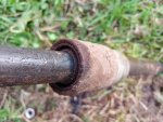
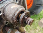
I removed the seal on the transmission main shaft by gripping it with pliers and rotating it until I could get it out. It's a metal flanged seal which reads NOK TC5 17 32 9 1.4. It's 17x32x9mm. I'm not sure I can find an exact replacement with a flange so I may just put this one back.
20211210_145114_HDR.jpg 20211211_193433.jpg

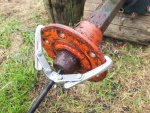
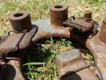
I removed both rear wheels. The big bolts on the hub (just one on each hub on my version) that screw against the axle were very hard to remove. I used a lot of penetrating oil and an impact wrench (tightening then loosening) and I managed to get the right side off. The left side was still stubborn. I tried using my gear puller but it was a bit small and I just sheared a bolt off. After a while I managed to knock it in with a hammer which then allowed me to use the impact wrench to remove the large bolt. Then I slowly knocked the hub off the axle.
20211210_161656_HDR.jpg 20211210_173717_HDR.jpg

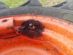
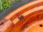
Both rear wheels had a bit of rust around the valves. But not too bad.
20211210_200923_HDR.jpg 20211210_201007_HDR.jpg

I made a cover for the air intake and hydraulic pump area out of wood. And I temporarily re-attached the exhaust manifold.
20211210_170210_HDR.jpg 20211210_173657_HDR.jpg
 
Last edited:

flangefrog

Member

Equipment
Kubota B6000
Nov 29, 2021
38
5
8
31
Auckland, New Zealand
I gave the engine a waterblast. The Aeroclean degreaser I used seemed to work pretty well compared to standard degreaser. It's a bit expensive though. Here are the before and after photos.

20211210_174100_HDR.jpg 20211210_183105_HDR.jpg
20211210_174107_HDR (1).jpg 20211210_183110_HDR.jpg

There's quite a bit of paint coming off the aluminium parts. I might take them off again so I can properly strip them and apply etching primer.
20211210_183130_HDR.jpg

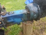
I gave the front axle and chassis a bit of a clean too.
20211210_183135_HDR.jpg

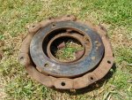
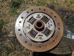
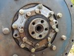
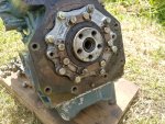
I removed the outer pressure plate, enabling the clutch plate to be removed and exposing the flywheel.
20211211_142249_HDR.jpg 20211211_142236_HDR.jpg 20211211_142228.jpg

There's a bit of wear on the clutch fingers. I'm not sure how flat they're supposed to be. I wonder if the clutch release bearing is not so great after all. New clutch fingers will cost $60 NZD. And a new bearing might be about the same. I don't think I'll replace it yet as I've never had an issue with the clutch.
20211211_142308_HDR.jpg
 
Last edited:

flangefrog

Member

Equipment
Kubota B6000
Nov 29, 2021
38
5
8
31
Auckland, New Zealand
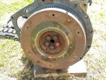
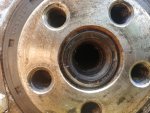
I removed the flywheel which exposes the rear engine seals. The large one (part 09560-00006) is NOK AH3399F which I believe is 66x88x9mm (I've also seen it listed as 8 or 10mm thick). It looks OK but I wonder if it's still worth replacing as it will be getting a bit old now. The small one (not clear but maybe 09400-16267?) says NOK AC0678E 2 which is 16x26x7mm. It seemed a little damaged on the outside - maybe while I was removing the engine? I'll replace this one.
20211211_142743_HDR.jpg 20211211_142847_HDR.jpg

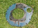
I removed the engine to bell housing plate. The gasket on this (only on the plate to bell housing side) seems in pretty good condition.
20211211_143351_HDR.jpg 20211211_143411_HDR.jpg

I had to buy a 5mm pin punch to remove one of the spring/roll pins holding a shaft onto the transmission. I also bought a bit more paint.

I'm pretty happy with the orange paint I've got. I prefer the older Kubota orange to the newer one, at least on this tractor. I found a dark grey paint which I liked. White Knight Squirts Metallic Charcoal Gloss. I've decided to paint the tractor dark grey, and paint the engine and radiator black with engine enamel. It won't look original but hopefully it will still look good and will protect it for some time. The engine almost doesn't need paint and could do with just a clear coat, but it should look just that little bit better with all the scratches covered.

I painted rust converter on the engine and the flywheel and clutch parts. I haven't taken any photos yet with the rain. I think I should have washed the rust converter off a bit sooner. Where there is just paint or clean metal and no rust, the rust converter doesn't dry properly but makes a thick glob that's a bit hard to get off.

I found a place local to me that sells rims/tyres/tubes. https://www.patchrubber.co.nz/. They seem to have a tube for the front wheels and possible for the rear also.

I removed the rear lift arms piston from the aluminium block and had a look at it. The o-ring was completely square - it should be round. There's a couple threads about replacement of these o-rings - here and here. They are on a B7100 and B7200 respectively. The first one doesn't use a back up ring, but the second one does. The o-ring for the B6000 is part 04810-08500, same as for the B7200. The parts book doesn't seem to mention a back up ring. I wonder if I should add one? I might bring this question to Waitemata Hydraulics when I next go there. Edit: one more article here.

I think I remember there were sometimes a few issues with the three point hitch like it dropping slowly and not being that powerful. The combination of changing out the o-rings and cleaning the filter will hopefully make that much better.
 
Last edited:

Nicksacco

Well-known member

Equipment
Kubota L35 TLB, 2014 RTV-1140CPX
Sep 15, 2021
686
395
63
Bahama, NC
Amazing work and great attention to detail!
This is a great log of a Kubota Sleeping Beauty!

Here are some thoughts and perhaps questions as I run thru all your notes:

Realistically speaking, no this isn't a museum piece, and therefore you are proceeding getting this monster back into the fields. I like your paint choices and I think primer and/or paint will be the best thing you can do to stop the decomposition!

Gear cases and such looked pretty good from what I saw. Get them as clean as you can and as you said the filter and new oil will work. You can also change the oil after a few hours and even install magnets in the gear cases to assist. Get some Neodymium if you can and you might not have to epoxy them depending on where you can place them - they are magnets after all.

I can't guess the extra lever. I'm sorry but can't figure it out. Have you tried sending a couple of pics and your questions to Kubota? Or a Kubota dealer?

The needle scaler is fabulous, but you do need decent cfm on the compressor. A small 10 gallon likley won't do well. My wheels were a mess and the frame looked like the wheels. Some of the frame I removed and rebuilt check this out (https://www.orangetractortalks.com/...-body-work-and-restoration.53846/#post-494447)

I think you're right about the coupler. If you wanted to, you could replace it at a later time - even by making new rubber bushings from something else.

My thoughts on the rear seal are the same. I'd hate for you to do all this work only to find out the rear engine seal is leaking.

The rear wheels have that nasty rust around the valve stems - but the tire is holding air - correct? Do you know if there's a tube in the rear?
I would hate for you to bang away at the rust only to open a hole. That's what happened to me on a freeze plug held together with rust-magnetism.

Wow the engine looks really good now that it's cleaned. This thing is becoming a giant kit and just require bolting together!

The rust converter doesn't do anything on paint - you're correct. It's a pain but all you can do is scrape it off.

One last thought is the clutch. I'm no expert but the fingers don't look worn to me. They look pretty thick - as thick as the rest of it anyway.

Off topic - I was watching the Rocket Lab's launch of the Electron rocket last week in Auckland and wonder if you were able to see anything of it.
Pretty amazing installation and company I think.
The other installation is Wallops VA - USA - I've been by there and it's very pretty country in that area called the DelMarVa (Delaware, Maryland, and Virginia)
 

flangefrog

Member

Equipment
Kubota B6000
Nov 29, 2021
38
5
8
31
Auckland, New Zealand
Putting magnets in the transmission is a good idea. Hopefully they might just stick on to a drain plug without moving as the surrounding is aluminium.

I don't yet know if the rear wheels have tubes yet but it looks like they might. I think the the holes are not too big in the rear wheels so I might use some fibre reinforced body filler for that. The front wheel really needs a plate welded in.

Yeah the clutch fingers are still fairly thick. From a few pictures I found it looked like maybe the surface touching the clutch release bearing was supposed to be a bit rounded rather than flat though?

I haven't actually seen any of Rocket Labs launches in person so far. I did look for one while I was visiting family down near the launch site but it was called off. I know someone who worked there as a propulsion engineer.

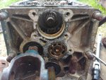
I took the front axle pivot pin out. It seems to have a little bit of play against both the chassis and the bushings in the diff. I think maybe all the surfaces are a bit worn including the pin but it's not that bad.
20211215_130624_HDR.jpg 20211215_204756_HDR.jpg 20211215_205621.jpg

The o-rings inside the bushes do look a little flat.
20211215_204647_HDR.jpg

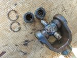
I took the front wheel drive universal joint apart. I can't remove the other half of the joint from the transmission case. It's rusted onto the shaft. I tried borrowing a two jaw gear puller but the centre pin didn't stay in the hole on the shaft and the jaws kept slipping off. Maybe a smaller gear puller would work.
20211215_133421_HDR.jpg

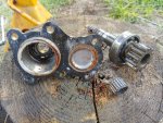
I removed the left and right axle covers.
20211215_171134_HDR.jpg 20211215_171122_HDR.jpg 20211215_171153_HDR.jpg

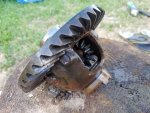
The axles can just be pulled out from the diff along with their bearings.
20211215_175033_HDR.jpg 20211215_175019_HDR.jpg
 
Last edited:

flangefrog

Member

Equipment
Kubota B6000
Nov 29, 2021
38
5
8
31
Auckland, New Zealand
There is a little chip on the four wheel drive engagement thing.
20211215_181746_HDR.jpg

I took the diff and bearings out. There was a little play in the left and right side small gears so they may need a shim.
20211215_191205_HDR.jpg 20211215_191231_HDR.jpg 20211215_191154_HDR.jpg


I took the first shaft out along with the cover.
20211215_192323_HDR.jpg 20211215_192351_HDR.jpg

I'm not sure I can take any more of the trans apart without splitting the diff off. And I don't want to do that until I know if I can get a hold of a new gasket because I don't want to mess with the spacing there.
20211215_204614_HDR.jpg

I've cleaned up a lot of the flanges. I saw the CRC gasket stripper said it can also be used to strip paint. But it's a bit expensive. I had some CRC paint stripper, so I used that and it worked quite well to strip the gaskets. I found that removing most of the thickness of the gasket first (possibly with a first application of paint stripper) and then applying the paint stripper to the thinner layer remaining worked best. It then basically slides off.
20211220_203411_HDR.jpg

I've done a bit of cleaning and prepping parts for paint. It's quite difficult to remove the paint from all the nooks and crannies in the aluminium casted parts, even when it's already flaking off and with paint stripper. I'm sure it would be a whole lot easier with a sandblaster.
20211220_203749_HDR.jpg
 
Last edited:

flangefrog

Member

Equipment
Kubota B6000
Nov 29, 2021
38
5
8
31
Auckland, New Zealand
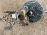
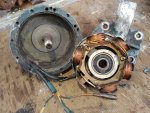
I took the alternator apart. I've seen a few different terms used on this forum (e.g. dynamo) but since this is a permanent magnet alternator, I think it is called a magneto.

First the fan is taken off with four bolts.
20211220_202328_HDR.jpg

The nut on the other side is removed along with a lock washer and conical washer (not sure if it's supposed to be conical?)
20211220_202349_HDR.jpg

The stator (with windings) is only held in the rotor (bell with magnets) by strong magnetism at this point. I used two flat head screwdrivers on opposing sides to pry it out (being careful not to scratch any windings) and then pulled it out with my hands once it was far enough. The bearing is an NSK 6201V which I believe is 12x32x10mm. There are a whole lot of replacements at Bearing Supplies ranging from $2.5 to $11.
20211220_203117_HDR.jpg

There has been various information I've found here about the alternator, charging and lights system, some of it accurate, and some of it less so. Here is my attempt to explain it.

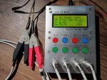
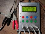
Here are some readings from testing the alternator at 1kHz. There is 2346µH inductance and 2.6Ω impedance between the white and yellow wires. There is 961µH and 1.39Ω between the brown and yellow wires. There is 1448µH and 1.83Ω between the brown and white wires. Getting closer to DC, the impedance/resistance at 100Hz is around 724mΩ, 305mΩ and 441mΩ respectively.
20211220_220446_HDR.jpg 20211220_220509_HDR.jpg 20211220_220529_HDR.jpg

The alternator is a single phase AC permanent magnet type with a tap at 2/5 of the winding length. You can see in the earlier photo that the windings are not symmetrical. There are six mechanical stator poles but only five have windings on. The solder joint on the left is the yellow wire, the one on the bottom is the white wire. If you look closely, there is a solder joint at 2/5 of the way around from the yellow wire which is connected to the brown wire.

These equations are almost correct, but not quite as the tap isn't at *exactly* 2/5:

~2346µH x 2/5 = ~961µH
~2346µH x 3/5 = ~1448µH

The impedance at 1kHz doesn't match the calculations so well, but the DC resistance matches pretty well.

Now we'll look at the "regulator". In fact, this is not actually a regulator but a solid state discrete bridge (full wave) rectifier.

Here is the rectifier as seen from the back of the dashboard and in the same orientation as seen on the wiring diagram. Top right is E (Earth). Right is B (Battery positive). Top left and bottom right are AC. Polarity of these doesn't matter since it's AC and it's being rectified.
20211220_234333.jpg

This is a look at the innards of the rectifier. The blue things are diodes. A bridge rectifier uses four diodes. One in each direction for each AC input and the other leg connected to the respective DC output. The two large things that stick out are electrically isolated heatsinks. You can see that the negative side of two diodes is connected to the case and E (earth) terminal and the positive side of the other two is connected to the B (battery positive) terminal.
20211220_234453.jpg bridge-rectifier-shunt-before.png

The alternator is wired up so that the brown wire (2/5 tap) is connected to one AC input of the rectifier. The Yellow wire is connected to the S terminal of the light switch which is also connected to the other AC input of the rectifier. So normally about 2/5 of the alternator winding length is connected to the rectifier and only 2/5 of the maximum power is available.

When the light switch is turned on, T and B are connected together, which joins the lights to the ignition (positive) terminal on the starter switch. G2 and S are also connected together. This in effect joins the white and yellow wire, putting the brown to yellow (2/5) and yellow to white (3/5) windings in parallel. This should increase the maximum power to 5/5 and I think the open circuit (maximum) voltage might increase by 25% (from 2/5 to 2.5/5).

This is all done so that the battery is not charged at too high a rate or voltage when the lights are not activated, and giving more power when activating the lights. It's a bit outdated. The better solution would be to have a simple solid state regulator module which includes a bridge rectifier and regulates the output voltage (and possibly the output current), simply drawing as much power as it needs at the time.

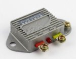
I already have one of these regulators that I bought a while ago. The JFT 149F 14V EQ140 for $13 shipped on eBay which is 14V and 1000W maximum. Like the original rectifier, it has the same four connections (three terminals and the case is for earth). It's much smaller than the original and is capable of far more power. An even smaller regulator could be made or bought. Edit: actually this is not quite the right regulator. It only has one AC input and the other terminal of the alternator is presumably connected to ground meaning this would only be a half-wave rectifier.
b6e3f891f5fdd34dc9f04a9bebb419c4_10609268-2.jpg

WIth a four terminal full wave regulator/rectifier the alternator wouldn't be connected to the light switch and would be connected straight to the regulator. The yellow and white wires could be connected together and connected to one AC terminal with the brown wire on the other like the original setup when the lights were turned on. Or the yellow wire could be connected to one AC terminal with the white wire to the other and the brown wire left disconnected.

Both methods would use the full windings, but the second one would have a higher maximum voltage. It would need to be confirmed that this higher voltage isn't above the regulators maximum rated input voltage though.

It would also be relatively easy to rewind this with the perfect open circuit voltage and with more power by using the sixth stator pole and maybe cramming a bit more copper in it.
 
Last edited:

Nicksacco

Well-known member

Equipment
Kubota L35 TLB, 2014 RTV-1140CPX
Sep 15, 2021
686
395
63
Bahama, NC
Hey Flange - so glad you got past the rain and posted more info!

Great photos of the work! I'm guessing that you're going to be in the assembly phase before too long.
If so, think about putting a Youtube video together once you get the beast running again. I'd like to see it running around the fields.

So you went and took down the gearboxes - can't say as I blame you on that. Once you assemble, you've know what you've got in there and have the expectations set rather than crossing your fingers and hoping! They look pretty good - I hope that all the bearings are in good shape. The rubber stuff - Orings and seals are just consumables eh?

That front pivot pin area actually doesn't look to bad. Do you think you can add some material (e,g., welding) to the pivot pin and turn it down to at least a consistent size through it's length? I'm just throwing out thoughts - it may not be bad enough to mess with.

If that uni joint isn't bad, then maybe leave it alone? Neither of us has a complete machine shop. Although is there an equipped auto shop that can split it for you? I'm sure you've thought of that already.

I haven't used the CRC paint stripper - does the kind you have contain dichloromethane? It's been banned here due to the dangers of the VOCs. I've used Aircraft Paint Remover and since it no longer has that chemical - it is not nearly as quick or effective as it used to be.

You're right about the paint removal from the nooks and crannies. I use soda to blast aluminum and it works very well. Sometimes the paint comes off easily and sometimes I have to use a paint remover first.
For steel and cast iron parts, I blast with coal dust (brand is called Black Diamond). If you have the time, you can use electrolysis on the ferrous metals too.

I don't know what differentiates a generator from an alternator. Is it that a generator has a spinning stator and an alternator has spinning magnets? In any case I get what you're thinking. Personally if you can improve the charging capabilities that's a good thing.

It sounds to me like they originally are using less of the available charging capacity (via the bridge rectifier) when lights are off to prevent overcharging the battery on the tractor whereas new (old) technology utilizes a regulator. Is that correct?

Do you think you'd want to go further and make a new bracket and simply add an alternator with built in rectifier/regulator? If enough room, you could still use the existing so you have the fan and use a longer fan belt. I guess if you already have the regulator - might as well use it.

The wheels are a pain, but at least you can utilize tubes so not to worry about air leaking. Once you get them in good shape whether with bondo or welding, they will work - at least they aren't bent, twisted or useless.

Great stuff, man! Keep it up!
 

Clementine21

New member

Equipment
B2401 with FEL, back blade, back rake, carry all
Dec 9, 2021
24
10
3
Troy, Idaho, USA
We've had pretty constant rain for the last several days so I haven't been able to do much. It looks like it should clear up by the weekend.

Thanks everyone for the kind words, nice to see a couple of others chiming in too.

Nick -
Most of the flanges I've put back together were bare metal after I cleaned them up. I was thinking that if they were closer there was more chance for them to rust together or cause galvanic corrosion. I think the silicone will stop most of it but you're right, it might be a good idea to paint them too.

I think whatever method I use I'll still get a bit of carbon or grit or something in the bearings, so I plan to give it another waterblast and then clean out the bearings with water displacement lube before filling it with oil. At least there's a bit of oil circulation and a filter so hopefully most of the loose particles should be caught.

The extra lever appears to have two positions. I really don't know what those could be. It doesn't control the centre PTO as that's fixed on the same shaft as the rear PTO. I may just end up disassembling the trans to take a look if nobody else knows.

That needle scaler looks like a useful tool. I think there may be an air compressor I could use but I can't justify buying a scaler at the moment. Hammer and a screwdriver gets the job done (slowly). I do have access to some angle grinders and a good range of wire brushes.

Good work on those wheels, they look a lot worse than mine although it doesn't look like those have holes in them.

I think what happened to the coupling is that the rubber is supposed to be thicker. But it's been compressed and expanded outwards so it's now thinner. I'm not sure I can obtain a new rubber peice right now so I'll just tighten it up. But it might result in a little less efficiency in decoupling engine pulsing from the transmission.

Clementine -
Thanks for sharing your experiences. I might do something similar for the muffler. Do you think 90W (or 80W like the manual) oil is a better choice than UTF for the front axle and steering box etc? With that gasket tip, is that just meant to score it or punch the hole right out? I did find that there are hollow punches which can be used to make the bolt holes - that was the part which seemed like it would be difficult to me when making a gasket by hand.

I have read about the reverse PTO. It's not a big issue to me as I don't expect to use it much. We do have a tiny flail mower that was used for it, and possibly a rotary tiller/cultivator as well. Both probably in very bad condition.

There is a PTO reverser I found available on Alibaba. The price doesn't seem to bad. The company also seems to make or sell many other reproductions of original Kubota (and other Japanese tractor) parts, even a copy of the original 3 point hitch setup.

Edinottawa -
I've read a bit about the "grey market" models and seen some pictures of the middle mount mower. As I understand it the grey market models are parallel imported while the US model was imported and sold by dealers. All of the Kubota B6000 tractors I've seen in NZ and several other countries seem to be the original Japanese model. Not sure if they were imported by dealers here but it doesn't really seem right to call them grey market models.

This tractor actually doesn't have a front splined PTO - though this could probably be added by bolting an adapter flange on to the the three threaded holes on the main engine pulley. And there is definitely a splined PTO available in the middle that runs off the same shaft as the rear PTO. You can see it in this photo with the clear tube that was on it. I think it's the same spline as the rear PTO. I wonder if this is one of the differences between the Japanese and USA versions?

I still don't own the tractor. I'm sure others will be wanting to use it once it's running but as long as it stays on the farm that's cool with me. Otherwise if I can't keep it here I'd take off some of the new parts I bought to resell them and replace with the originals. Then it won't be so attractive any more. It's still worth it for the experience as I'm learning a lot.

---------------------

Apart from the mystery lever I still have another question that needs answering, and that's about the wheel size. I've broken that out into another thread:

I also want some more info about the two way cock for aux hydraulics connection. I've made a thread here:

I removed the glow plugs (which both seemed ok), did a lot of research on them and made yet another thread:

Now back to my log. Here's what I did in the two or three days before it started raining.

I removed the seal on the transmission main shaft by gripping it with pliers and rotating it until I could get it out. It's a metal flanged seal which reads NOK TC5 17 32 9 1.4. It's 17x32x9mm. I'm not sure I can find an exact replacement with a flange so I may just put this one back.
View attachment 71477 View attachment 71476

I removed both rear wheels. The big bolts on the hub (just one on each hub on my version) that screw against the axle were very hard to remove. I used a lot of penetrating oil and an impact wrench (tightening then loosening) and I managed to get the right side off. The left side was still stubborn. I tried using my gear puller but it was a bit small and I just sheared a bolt off. After a while I managed to knock it in with a hammer which then allowed me to use the impact wrench to remove the large bolt. Then I slowly knocked the hub off the axle.
View attachment 71478 View attachment 71479

Both rear wheels had a bit of rust around the valves. But not too bad.
View attachment 71481 View attachment 71480

I made a cover for the air intake and hydraulic pump area out of wood. And I temporarily re-attached the exhaust manifold.
View attachment 71483 View attachment 71482
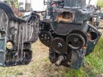
Making gaskets with ball-p hammer (autocorrect wants 'pine'!) I only used the hole punches on very small bolts, less than 10mm. Takes a bit of practice, but I could get some very clean gaskets for non-pressurized applications. (Been doing it for over 60 years, maybe that helps!) I always used good quality 80-90w in the front axle. Keep up the great work. Good to hear that parts are available in the rest of the world. Dealers here said 20 years ago that things like the oil bath air cleaner bowl were no longer available.