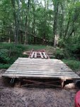
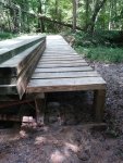
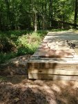
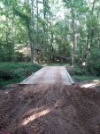
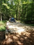
Thought I'd share my bridge project. On our family land, there's about 30 - 40 acres cut off by a running stream that, over the years, has developed 8 to 10 ft high banks. This has prevented equipment access for maintaining trails etc. Maybe 20 years ago, Dad threw a culvert in and covered it with local soil but within a year it had washed out. About 5 years ago we had timber cut and a neighbor let the loggers haul across him but this wasn't a long-term solution.
So, newly retired and with a little money from the timber sale, I decided a bridge would be a good project. I wanted it capable of supporting a pickup truck and tractor with bush hog or other attachments. (Sorry, at the time we didn't have the Kubota L35, so you'll see blue here.) So I started with a 6,000# live load design. The site is accessed from a trail that doesn't allow heavy equipment, concrete truck, etc. This meant headwalls wouldn't be practical. Therefore it's supported on pads set back from the bank edge. This increased the span, but made the project more DIY'able.
1. I calculated using W16x26# beams at 36,000 psi yield strength. But when I contacted the steel supplier, I was pleasantly informed that 50,000 psi was standard. So the final product has about 11,000# live load capacity. I was in a bit of a hurry and wasn't sure I'd even be able to get the beams across the ditch, so I didn't fab and weld clips on before proceeding. The beams were delivered to a clearing on top of the hill.

Rolled a coat of red primer all over.

When they were dry, I dragged them down to the site.
2. There was a fair sized tree on the other side, so I anchored a wire cable on it as high as I could reach, went to a block chained to the beam, back to a block chained up the tree and then to the pull tractor. This gave me a 2:1 advantage. Throughout this process I made sure to keep the beams blocked up. Sweetgum sap is an amazing lubricant!
 i
i
(It was while dragging the rigging across the ditch that my sister showed up to check on progress. When she asked why I stopped, literally, mid-stream I had to tell her I was staring down a water moccasin. He eventually tired of the game and slithered off.)
I ended up using the tractor as a movable anchor and pulling the tow line like a bow string to move the beam. This let me yank it to pop the end of the beam up as it got near the far side and tended to drop. Without too much trouble, both beams were across and laying on cribbage.

These lightweight beams are narrow and not very stiff laterally. You can see the bow under their own weight. But they are strong enough to carry me and a wheelbarrow of concrete.
3. I planned on 6'-8" between the beams. This put them just outside tractor and truck tread and allowed me to cut the 20' cross bracing angles in thirds. So I formed 2 ft square x 8" thick pads with 2 layers of wire mesh and, with the help of my sister and brother-in-law, mixed and poured concrete. We put 2 anchor bolts in each pad.
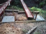
4. After the concrete cured, it was time to set the beams in place.
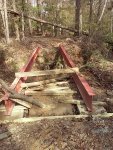
Using a lever, it wasn't too hard to get them in place, but standing them up was another matter. I wrapped a chain around the near end and used the tractor lift to twist it. But besides limber, these beams are also 'twisty'. Just as the far end nears vertical, it springs through and the whole thing ends up laying on the other side. But eventually they were standing up and braced against turning over.
5. The next step was installing cross-bracing. Since these beams are limber laterally, they require quite a bit of bracing to develop their full strength - 5 feet.
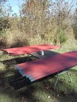
I cut 2x2x1/4 angle and primed it for bracing. Since I had decided to weld the bracing instead of welding on clips and bolting the bracing to them, the braces required some tricky angle cutting. If I were doing this again, I'd use clips and bolts.
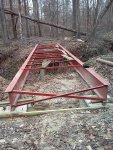
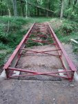
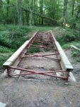
I welded the braces on each end and laid the others out to use to support some boards so I could cross to do some clean up work. One of the boards broke, I fell through, broke my arm, slight concussion, surgery, recovery, etc. Besides the delay in construction, it cemented my decision to hire professionals to do the cross-brace welding. After they finished, we had this frame:
(See Part 2, can't attach more pictures)
So, newly retired and with a little money from the timber sale, I decided a bridge would be a good project. I wanted it capable of supporting a pickup truck and tractor with bush hog or other attachments. (Sorry, at the time we didn't have the Kubota L35, so you'll see blue here.) So I started with a 6,000# live load design. The site is accessed from a trail that doesn't allow heavy equipment, concrete truck, etc. This meant headwalls wouldn't be practical. Therefore it's supported on pads set back from the bank edge. This increased the span, but made the project more DIY'able.
1. I calculated using W16x26# beams at 36,000 psi yield strength. But when I contacted the steel supplier, I was pleasantly informed that 50,000 psi was standard. So the final product has about 11,000# live load capacity. I was in a bit of a hurry and wasn't sure I'd even be able to get the beams across the ditch, so I didn't fab and weld clips on before proceeding. The beams were delivered to a clearing on top of the hill.

Rolled a coat of red primer all over.

When they were dry, I dragged them down to the site.
2. There was a fair sized tree on the other side, so I anchored a wire cable on it as high as I could reach, went to a block chained to the beam, back to a block chained up the tree and then to the pull tractor. This gave me a 2:1 advantage. Throughout this process I made sure to keep the beams blocked up. Sweetgum sap is an amazing lubricant!
 i
i(It was while dragging the rigging across the ditch that my sister showed up to check on progress. When she asked why I stopped, literally, mid-stream I had to tell her I was staring down a water moccasin. He eventually tired of the game and slithered off.)
I ended up using the tractor as a movable anchor and pulling the tow line like a bow string to move the beam. This let me yank it to pop the end of the beam up as it got near the far side and tended to drop. Without too much trouble, both beams were across and laying on cribbage.
These lightweight beams are narrow and not very stiff laterally. You can see the bow under their own weight. But they are strong enough to carry me and a wheelbarrow of concrete.
3. I planned on 6'-8" between the beams. This put them just outside tractor and truck tread and allowed me to cut the 20' cross bracing angles in thirds. So I formed 2 ft square x 8" thick pads with 2 layers of wire mesh and, with the help of my sister and brother-in-law, mixed and poured concrete. We put 2 anchor bolts in each pad.

4. After the concrete cured, it was time to set the beams in place.

Using a lever, it wasn't too hard to get them in place, but standing them up was another matter. I wrapped a chain around the near end and used the tractor lift to twist it. But besides limber, these beams are also 'twisty'. Just as the far end nears vertical, it springs through and the whole thing ends up laying on the other side. But eventually they were standing up and braced against turning over.
5. The next step was installing cross-bracing. Since these beams are limber laterally, they require quite a bit of bracing to develop their full strength - 5 feet.

I cut 2x2x1/4 angle and primed it for bracing. Since I had decided to weld the bracing instead of welding on clips and bolting the bracing to them, the braces required some tricky angle cutting. If I were doing this again, I'd use clips and bolts.

I welded the braces on each end and laid the others out to use to support some boards so I could cross to do some clean up work. One of the boards broke, I fell through, broke my arm, slight concussion, surgery, recovery, etc. Besides the delay in construction, it cemented my decision to hire professionals to do the cross-brace welding. After they finished, we had this frame:
(See Part 2, can't attach more pictures)
Attachments
-
458.7 KB Views: 2,076
-
507.7 KB Views: 1,652
Last edited:


