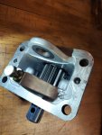
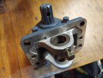
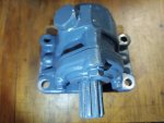
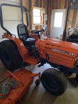
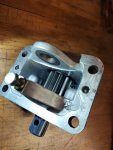
I am the third owner of a B8200 Kubota with a mid mount mower. Before I started to mount the mower I thought I'd better take off the mid mount PTO shaft cover to make sure it actually turns. Which to my surprise it didn't (however the rear PTO does turn). After I drained the hydraulic fluid and looked inside I found the PTO was missing parts 8, 9, 10 and 11 in the attached parts diagram. The bottom half the the PTO is all in place and looks good. Also the gears above in the case look good. Apparently one of the owners before me had a problem and could not get the hard to find parts and so he re-attached the bottom case and decided to "throw in the towel".
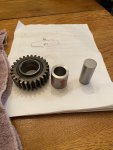
Through checking with various nationwide Kubota Dealers, I was able to find all the parts except for part #9 in the diagram below. I have a relative who is a 40 year machinist and he said he can make the "idle shaft" (part #9). On first inspection and measuring the parts that I do have, my relative has questions that I hope you guys can help me out with....They are.
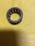
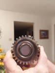
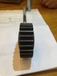
1. Part #10 (needle roller bearings in photo below) He can make an idle shaft that will fit into the casing holders (part #2) and it will also fit snugly inside the two roller bearings. However part #8 (the gear) inside opening will be loose over the needle roller bearings and he thinks this will tear things up. He is wondering if he needs to make a sleeve for inside the gear so it fits and turns snugly over the needle bearings????
2. When he installs parts 8, 10 and 11 on the shaft, there will be a side to side movement of about 1/8" between the shaft mounting posts on the PTO case. He is a little concerned that this might be a problem????
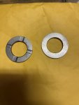
3. Part #11 (2 collars in diagram below) one side has 4 notches and the other side is flat. Which side goes on the shaft against part #8 (gear) the flat side or notched side????
I really appreciate any technical help you guys can give to get this PTO working properly.
Attachments
-
232.4 KB Views: 111
-
307 KB Views: 73
-
389.3 KB Views: 67


