torch
Well-known member
Equipment
B7100HSD, B2789, B2550, B4672, 48" cultivator, homemade FEL and Cab
I'm trying to figure out the hydraulics in anticipation of adding a FEL.
The WSM calls the hydraulic system control type a "closed centre type" under the general specifications. However, the pump seems to be a fixed-displacement gear pump and in the description of the control lever functions, it states
"with the hydraulic control lever at neutral, oil is pressure-fed from the pump through the space between the valve body and the spool big end to the body cover. It then returns to the return port of the valve body."
Is this not the description of an open centre type?
Next question: I have read in at least two threads here that the B7100-HST has a 4 gpm hydraulic pump, as opposed to the 3 gpm pump of the original B7100. However, the WSM indicated the pump delivers 11.2 lpm, which is actually less than 3 gpm. Is there any documented update at a specific serial number or date? EG: The WSM I have has an inserted section ("G1") documenting a 1990 change of the HST. Or is this a matter of an honest error being repeated often enough to seem true?
Several threads mention the possibility of swapping in the higher volume pump from a B8200. But apparently there's at least 3 different B8200 pumps. Can anyone confirm that the correct pump would be the one driven from the injection pump, part number 67111-76103?
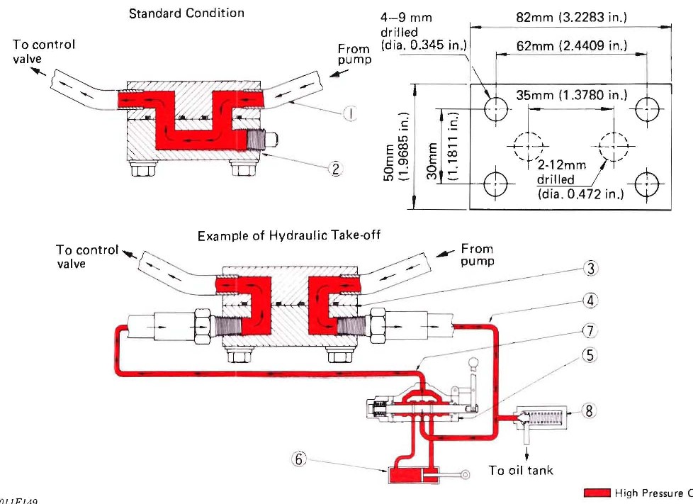
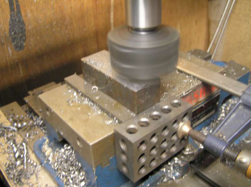
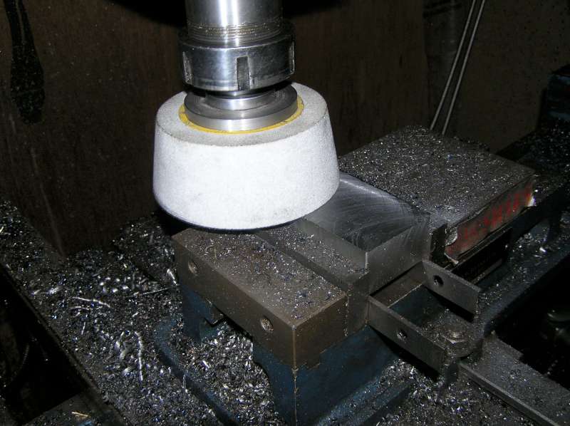
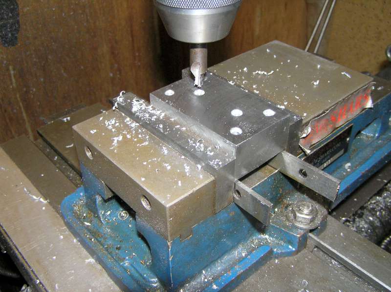
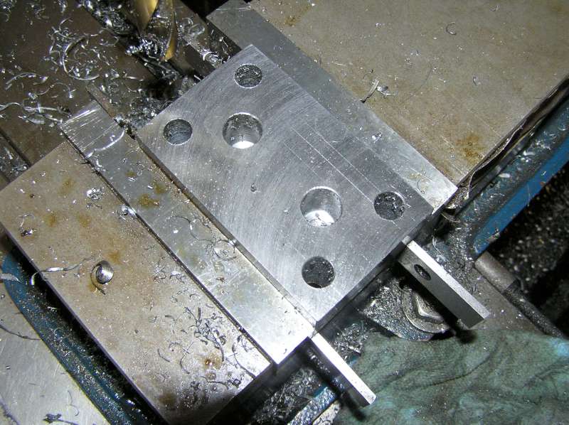
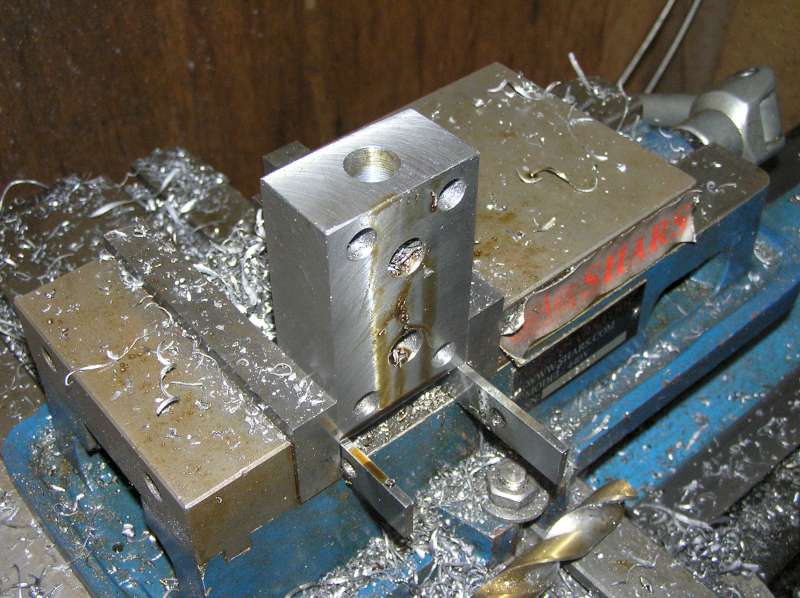
The diverter valve under the seat can be used to operate a second hydraulic function (single acting) from the existing control valve instead of lifting the 3ph. Alternatively the "hydraulic block" can be tapped by removing the cover and replacing it with the "impement hydraulic cover". I assume this is a Kubota-specific part? Does it only come with Kubota-brand implements? There's a dimensioned sketch in the WSM adjacent to the flow diagrams, and the diagrams seem to show the o-rings are in the retained half of the block -- is the cover as simple as drilling/tapping some holes in a block of steel?
Do I understand correctly that to tap into the hydraulic block would then necessitate an implement open centre spool valve fed from the pump side of the hydraulic block and "power beyond" function piped back to the 3ph side of the hydraulic block, plus a third line from the implement relief valve discharge back into the reservoir?
How does one normally deal with fluid flow to remove the FEL? Mount the spool valve to the FEL and couple the tractor side hoses to each other to complete the circuit? Or is it preferable to mount the spool valve to the tractor so there is no chance of dead-heading the hydraulic system?
I will probably have more questions, but my grandson just arrived and hopped up onto my knee...
Last edited:


