Determining bevel gear clearance

G Crawford

New member

Equipment
Kubota L3010
Jun 4, 2022
26
5
3
Knoxville, TN
Hi: I have the front axle of my L3010D HST apart except for the diff. The bottom bevel gears both had damaged teeth with a lot of metal filings in the bottom of the housings. I have the two bevel gears, bearings, and axle seals ordered. The 42 tooth gears are in good shape. The service manual states to place "fuse" (I am assuming this means plastigage) in three places on the gear teeth and then to carefully rotate the gear to determine back lash/clearance and insert different thicknesses of shims behind the bearing to arrive at the proper clearance.

Here's my question: Is the plastigage placed on a gear tooth face, or in the valley between the teeth?

Thanks.
 

woodman55

Well-known member

Equipment
L6060HSTC, RTV 1100
May 15, 2022
927
721
93
canada
I checked my L6060 manual and it reads the same, and it points to the side of the tooth. My concern would be the plastigage getting wiped/damaged. I would think you would need to put it on the "coast" side, to measure the lash. You can try the gears by hand, but I don't think the teeth would ever touch bottom, so putting the plastigage in the valley would not accomplish anything.
 

Henro

Well-known member

Equipment
B2910, BX2200, KX41-2V mini Ex., Beer fridge
May 24, 2019
5,781
2,965
113
North of Pittsburgh PA
The service manual states to place "fuse" (I am assuming this means plastigage) in three places on the gear teeth and then to carefully rotate the gear to determine back lash/clearance and insert different thicknesses of shims behind the bearing to arrive at the proper clearance.
Just for educational purposes, how does one keep the plastigage on the face of a gear tooth?

I can see how one would use plastigage to measure main and rod bearing clearance, but can't visualize what would hold the plastigage on three gear teeth, when the gear is rotated.
 

NorthwoodsLife

Well-known member
Lifetime Member

Equipment
Kubota B7100(sold), Kubota LX2610 Cab
Oct 15, 2021
1,053
1,002
113
Wisconsin
Sounds like gear marking compound is what you need. It's used for similar measurements to Pastiguage, but resultant measurements are determined very differently.
I'd try gear marking compound and shim away.

I've used it on diffs, which is over kill on a tractor front axle.
 

ejb11235

Well-known member

Equipment
BX23S, Braber BBR4G 4' Box Blade & LRM5G 5' landscape rake
Jan 20, 2022
452
327
63
Seattle, WA, USA
Sounds like gear marking compound is what you need. It's used for similar measurements to Pastiguage, but resultant measurements are determined very differently.
I'd try gear marking compound and shim away.
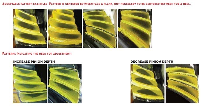
This is cool. I have no experience adjusting differentials, so I looked up "gear marking compound" and landed on this page ... https://www.yukongear.com/blogs/how-to-create-read-ring-gear-patterns_1

I've read about this before and it refreshed my memory that the goal is to properly position the wiping pattern on the ring gear that is created by its mechanical interaction with the pinion gear. I've included a picture from that web page.

Again, from the web page cited above:
1. Use shims to move the ring gear closer to the pinion gear to decrease backlash.
2. Use shims to move the ring gear farther from the pinion gear to increase backlash.
3. Use shims to move the pinion closer to the ring gear to move the drive pattern deeper on the tooth (flank contact) and slightly toward the toe. The coast pattern will move deeper on the tooth and slightly toward the heel.
4. Use shims to move the pinion further away from the ring gear to move the drive pattern toward the top of the tooth (face) and slightly toward the heel. The coast pattern will move toward the top of the tooth and slightly toward the toe.
 

TheOldHokie

Well-known member
Lifetime Member

Equipment
L3901/LA525, B7200DT/B1630, G2160/RCK60, G2460/RCK60
Apr 6, 2021
8,725
4,465
113
Myersville, MD
windyridgefarm.us
This is cool. I have no experience adjusting differentials, so I looked up "gear marking compound" and landed on this page ... https://www.yukongear.com/blogs/how-to-create-read-ring-gear-patterns_1

I've read about this before and it refreshed my memory that the goal is to properly position the wiping pattern on the ring gear that is created by its mechanical interaction with the pinion gear. I've included a picture from that web page.

Again, from the web page cited above:


Non-drying machinist's blue aka Prussian blue is available at most auto parts stores and commonly used for differential setup. The procedure is described in many of my workshop manuals.

Dan

1656668765551.png
 
Last edited:
  • Like
Reactions: 1 user

woodman55

Well-known member

Equipment
L6060HSTC, RTV 1100
May 15, 2022
927
721
93
canada
Just for educational purposes, how does one keep the plastigage on the face of a gear tooth?

I can see how one would use plastigage to measure main and rod bearing clearance, but can't visualize what would hold the plastigage on three gear teeth, when the gear is rotated.
grease. The procedure reads to use grease.
 

TheOldHokie

Well-known member
Lifetime Member

Equipment
L3901/LA525, B7200DT/B1630, G2160/RCK60, G2460/RCK60
Apr 6, 2021
8,725
4,465
113
Myersville, MD
windyridgefarm.us
grease. The procedure reads to use grease.
Hi: I have the front axle of my L3010D HST apart except for the diff. The bottom bevel gears both had damaged teeth with a lot of metal filings in the bottom of the housings. I have the two bevel gears, bearings, and axle seals ordered. The 42 tooth gears are in good shape. The service manual states to place "fuse" (I am assuming this means plastigage) in three places on the gear teeth and then to carefully rotate the gear to determine back lash/clearance and insert different thicknesses of shims behind the bearing to arrive at the proper clearance.

Here's my question: Is the plastigage placed on a gear tooth face, or in the valley between the teeth?

Thanks.
I dont know how that measures backlash. Rotating the gears brings them into direct contact completely smashing the plastigage. Gesr backlash is defined as radial travel and typically measured as shown below.

Dan

1656675481144.png
 

G Crawford

New member

Equipment
Kubota L3010
Jun 4, 2022
26
5
3
Knoxville, TN
Dan, you are correct. I think they are using plastigauge because there is no way to measure backlash on the bevel gears. Nothing is open to facilitate using a dial indicator, and there is a lot of slop on the splined input/output shafts, so you couldn't check it there. Gear marking compound may be the better option.
As Northwoods Life said, it's probably overkill on a tractor, whose gears are whining all the time anyway. I just want to make sure I don't destroy anything by being way out of adjustment. The range is (roughly) in inches .006 to .014.

Thank you everyone for the replies. I'll go get some prussian blue.
 

hagrid

Well-known member
Lifetime Member

Equipment
K1600GTL, ZX-14R
Jun 11, 2018
930
1,196
93
Pittsburgh
If mammary serves the shop manual specifies the use of "the soft soldering wire" for verifying lash on the BX final drive.
 
  • Like
Reactions: 1 user

woodman55

Well-known member

Equipment
L6060HSTC, RTV 1100
May 15, 2022
927
721
93
canada
Sounds like gear marking compound is what you need. It's used for similar measurements to Pastiguage, but resultant measurements are determined very differently.
I'd try gear marking compound and shim away.

I've used it on diffs, which is over kill on a tractor front axle.
I dont know how that measures backlash. Rotating the gears brings them into direct contact completely smashing the plastigage. Gesr backlash is defined as radial travel and typically measured as shown below.

Dan

View attachment 82674
you would need to put it on the coast side, not the driven side. That's the only way I can see it working. As Hagrid mentioned, solder would do the same trick.
 

woodman55

Well-known member

Equipment
L6060HSTC, RTV 1100
May 15, 2022
927
721
93
canada
I would say the main thing to verify is that the teeth are not touching the coast side of the teeth when they are coming into and out of contact.
 

Henro

Well-known member

Equipment
B2910, BX2200, KX41-2V mini Ex., Beer fridge
May 24, 2019
5,781
2,965
113
North of Pittsburgh PA
you would need to put it on the coast side, not the driven side. That's the only way I can see it working. As Hagrid mentioned, solder would do the same trick.
Very interesting comment. But is this actually true? At first look seems to be.

BUT during the test, there is going to be some space between the two surfaces, so if the measurement is done by deformation of material placed withing the space, would not the net effect be the same on either side?

Seems like the material would be compressed to the same point, when turning the gears manually, regardless of what side it was placed on.
 
  • Like
Reactions: 1 user

TheOldHokie

Well-known member
Lifetime Member

Equipment
L3901/LA525, B7200DT/B1630, G2160/RCK60, G2460/RCK60
Apr 6, 2021
8,725
4,465
113
Myersville, MD
windyridgefarm.us
Very interesting comment. But is this actually true? At first look seems to be.

BUT during the test, there is going to be some space between the two surfaces, so if the measurement is done by deformation of material placed withing the space, would not the net effect be the same on either side?

Seems like the material would be compressed to the same point, when turning the gears manually, regardless of what side it was placed on.
When the gears are turned the space (gear lash) on the drive side is reduced to ZERO and the teeth are in direct metal to metal contact. The teeth on the coast side are separated by the gear lash.

Dan
 

Henro

Well-known member

Equipment
B2910, BX2200, KX41-2V mini Ex., Beer fridge
May 24, 2019
5,781
2,965
113
North of Pittsburgh PA
When the gears are turned the space (gear lash) on the drive side is reduced to ZERO and the teeth are in direct metal to metal contact. The teeth on the coast side are separated by the gear lash.

Dan
Sure, but if something takes the space on either side, what difference does it make what side it is on?

This is my point...
 

TheOldHokie

Well-known member
Lifetime Member

Equipment
L3901/LA525, B7200DT/B1630, G2160/RCK60, G2460/RCK60
Apr 6, 2021
8,725
4,465
113
Myersville, MD
windyridgefarm.us
Sure, but if something takes the space on either side, what difference does it make what side it is on?

This is my point...
I guess I missed your point. I thought you were suggesting measuring on the drive side.

Measuring space on the coast side is equivalent to gear lash only if the tooth profile is symmetric. I do not know if that is true. I do know a dial indicator will get you the correct measurement.

Dan
 

Henro

Well-known member

Equipment
B2910, BX2200, KX41-2V mini Ex., Beer fridge
May 24, 2019
5,781
2,965
113
North of Pittsburgh PA
I guess I missed your point. I thought you were suggesting measuring on the drive side.

Measuring space on the coast side is equivalent to gear lash only if the tooth profile is symmetric. I do not know if that is true. I do know a dial indicator will get you the correct measurement.

Dan
I think what I was suggesting is that there is a certain amount of space between the surfaces of the gears, if they can be turned, and that when measuring that space with a substance, while turning by hand or slowly with some power source, regardless of which side the deformed material is on, it would be deformed the same amount.

This is just an intellectual question/observation on my part. I could be missing something.

I think the tooth profile would be symmetric, since the design must work in both directions of rotation.
 

TheOldHokie

Well-known member
Lifetime Member

Equipment
L3901/LA525, B7200DT/B1630, G2160/RCK60, G2460/RCK60
Apr 6, 2021
8,725
4,465
113
Myersville, MD
windyridgefarm.us
I think what I was suggesting is that there is a certain amount of space between the surfaces of the gears, if they can be turned, and that when measuring that space with a substance, while turning by hand or slowly with some power source, regardless of which side the deformed material is on, it would be deformed the same amount.

This is just an intellectual question/observation on my part. I could be missing something.

I think the tooth profile would be symmetric, since the design must work in both directions of rotation.
If you put plastigage on the drive side of a tooth and turn the gears the teeth will close up against one another, lash is going to go to zero, and the plastigage is going to be shredded. No???

Dan