Summit 3rd Function Kit Install on Kubota B2650

bird dogger

Well-known member
Vendor Member

Equipment
Kubota B2650 and lots of other equipment
Feb 24, 2019
1,625
1,509
113
North Dakota
I decided to add a 3rd function kit to the tractor for an upcoming grapple addition. Since humans install them at the dealership, I figured I should be able to do the same in my shop and save a few dollars. Plus, with most everything shut down it provides something to do and a reason to get educated on the tractor’s hydraulic system. After some looking and thinking, the B2650 kit from Summit Hydraulics was ordered.

Having the BH77 backhoe might also require some adjustments/alterations to be accounted for. At the very least it would be an expensive learning experience. More realistically, I figured it wouldn’t be that hard, I could learn something, and might even save a couple of dollars. The best part would be having done the work…..it’d be easier to trouble shoot down the road knowing how and where the components are and how they function together.

A few people had recently expressed interest in this kit and adding a 3rd function themselves. So, I decided to take some pics hoping it may might help someone in their own decision-making process. Studying the WSM beforehand helped to understand the hydraulic system layout and confirm where the power beyond port was and what needed to be done to cut into the hydraulic system.

Looking at individual component prices it appears that one can’t beat the kit prices offered. Those individual prices start to add up quickly! Thus the “kit” arrived and there was no turning back.

I need to sort and resize some pics and will soon start posting the progress.
 
  • Like
Reactions: 1 user

Bill Groom

Member

Equipment
B7100 HST
Apr 2, 2019
115
0
16
N.E. Ohio
Looking forward to this, considering the same kit myself. Good luck, and please keep us posted!

Sent from my SM-N976V using Tapatalk
 

bird dogger

Well-known member
Vendor Member

Equipment
Kubota B2650 and lots of other equipment
Feb 24, 2019
1,625
1,509
113
North Dakota
Looking forward to this, considering the same kit myself. Good luck, and please keep us posted!

Sent from my SM-N976V using Tapatalk
Hi Bill,
Thanks for your interest!! I'll be posting pics of the whole install and one piece I had to fabricate in order to keep the backhoe (BH77) hookups as close to the same as possible. It's not going to take that long....I hope. :eek:

Regards,
David
 

bird dogger

Well-known member
Vendor Member

Equipment
Kubota B2650 and lots of other equipment
Feb 24, 2019
1,625
1,509
113
North Dakota
The kit instructions are pretty generic in that every single step isn’t laid out in a paint by numbers type format. But there aren’t that many total parts and from the pictures it’s fairly easy to separate them into the three groups: valve body assembly, front end quick couplers and hoses, and the power beyond and tank fittings and hoses. You get to choose your own coupler layout and positions. A loose fit dry run to make sure you have all the right fittings in all the right places might be a good idea.

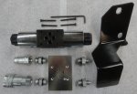
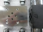
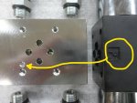
Here’s the main valve body/block and parts, plus the mounting bracket. The main block ports are nicely marked as P, T, A&B. You do have to pay attention and make sure the letter P on the electric valve assembly is lined up with the indexing hole on the main hydraulic block as indicated with the yellow arrow. Those two parts are assembled together with 4 allen head screws. Here’s some pics:

Summit Valve Assembly.jpg

P Orientation to Block.jpg

P Orientation to Block_2.jpg

Valve Block Labels.jpg

Valve Block Mounting Holes.jpg

The P (Power Beyond) and T (Tank) fittings are #6JIC fittings that match the supplied hose (3/8 inch) swivel fittings.

The A&B port fittings are O-ring fittings to match both the block to the supplied quick couplers. I don’t think the instructions ever mentioned the exact name of those fittings but they were the only ones that fit during that loose fit dry run mentioned above.

In the end it really doesn’t matter how you lay out your hose quick couplers as long as you match them with the appropriate hose quick couplers. With the ports all on the two sides it does make for a nice compact layout and install as you'll soon see.

And cleanliness is the order of the day once you start opening up your hydraulic system!!
 
  • Like
Reactions: 1 user

bird dogger

Well-known member
Vendor Member

Equipment
Kubota B2650 and lots of other equipment
Feb 24, 2019
1,625
1,509
113
North Dakota
The hardest part of the install was deciding to take the plunge and do it. Making sure one knows exactly which port is the Power Beyond on the loader valve was determined by scouring the WSM and making sure the pics and hookups matched exactly how the tractor was hooked up. I followed the pressure output line from the hydraulic pump. The loader valve hydraulic piping was easy to follow back to the loader valve. That left the PB (power beyond) out of the loader valve that fed the 3 pt. hitch hydraulics. I couldn’t find any markings that were supposed to identify the PB port on the loader valve. No stampings or green dot. Maybe they were buried under all the paint layers. But everything matched between the WSM, the tractor, and the Summit instructions.

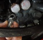
I hit a snag right away. Dang!! I didn’t have a wrench to loosen and remove the piping off of the PB. I wasn’t going to use an adjustable wrench so off to town to buy a 26mm socket. The only one in stock was for a ¾ inch drive but it turned out that was perfect. It took a ¾ inch breaker bar to loosen those fittings. Whoever had installed the back hoe hydraulic piping on my tractor had really reefed on those bolts! That 26mm socket was the only odd ball size and only needed for removing the bolts from the banjo fittings on the piping located on the power beyond and the 3 pt hitch port. Here’s some pics of those fittings:
PB to Tank Pipe to Remove.jpg
26MM Socket.jpg

Since my tractor was set up with a backhoe, part of the work was already done. The backhoe hookups get installed between the PB and the 3 pt. hitch ports (originally). And since the backhoe return line connects to the 3 pt. hitch port, that connection stayed as is. But the connection between the PB and the backhoe now gets changed. The PB now goes to the P port on the summit valve and the summit T port now goes back to the backhoe hydraulic input hose. Essentially an inline hydraulic circuit: PB port to the Summit valve P port. Then out of the Summit T port to the backhoe hydraulic input hose. Then out of the backhoe return line to the 3 pt hitch port (which was already in place). The same backhoe quick couplers still being used. However, that required a different adapter and a means of attaching that adapter to the backhoe subframe to keep the backhoe’s hookup as close to original as possible.

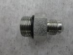
The original solid piping gets discarded and the backhoe coupler now has to attach to the kit’s JIC swivel hose end. A simple adapter (3/8 male NPT to #6 JIC) welded to a bracket to mimic the original layout solved the issue.

If you don’t have the backhoe the installation is that much simpler. But you still need that 26mm wrench/socket to remove those banjo fittings. The kit supplied fittings will then connect and adapt the PB and 3 pt. hitch ports to the supplied hydraulic hoses that get routed to the Summit P and T ports. That will become apparent shortly. But if you do have a backhoe, here’s a few pics of the simple adapter and bracket I fabbed up for the install. That fitting was only a couple of bucks.
PB to Backhoe Removal.jpg
Backhoe Power Beyond Removal.jpg
Fabricated Backhoe Fitting.jpg

Next up: The PB hookup
 
  • Like
Reactions: 1 user

bird dogger

Well-known member
Vendor Member

Equipment
Kubota B2650 and lots of other equipment
Feb 24, 2019
1,625
1,509
113
North Dakota
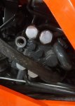
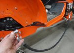
Here’s a pic of the exposed PB port on the B2650 after removing the hydraulic piping per the Summit instructions.
B2650 PB Port.jpg PB and T Adapters.jpg
PB Adapter.jpg

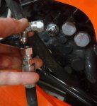
The port adapter along with a 90 degree elbow connected to the hose that connects to the Summit valve P port. All are included in the kit. The pic showing the hose connected to the Summit valve port P was taken pre final installation where it was routed underneath and secured.
PB Hose and Elbow.jpg PB Hose Pre Routing.jpg

Not sure what's coming up next. It's all downhill from here. Except for one speed bump coming up later. :eek:

I forgot to mention but it's probably obvious that the right rear tire has been removed and this provides adequate access to do the hydraulic plumbing, hose routing, control wiring, etc. Stay tuned. and thanks for lookin'

david
 
  • Like
Reactions: 1 user

B737

Well-known member
Lifetime Member

Equipment
LX3310
Jun 9, 2019
2,024
2,200
113
USA
Great job Dave!
It is surprising how many people defer this to the dealer, and it's really not that bad to get done. Admittedly, I used the wrong ports during my first go, but sorted that out (thanks to eserv and this forum). Having a DIY like this will be valuable to so many members in the future when they go searching. Looking forward to following your project. Nice job wrapping the hoses too.
 

bird dogger

Well-known member
Vendor Member

Equipment
Kubota B2650 and lots of other equipment
Feb 24, 2019
1,625
1,509
113
North Dakota
Great job Dave!
It is surprising how many people defer this to the dealer, and it's really not that bad to get done. Admittedly, I used the wrong ports during my first go, but sorted that out (thanks to eserv and this forum). Having a DIY like this will be valuable to so many members in the future when they go searching. Looking forward to following your project. Nice job wrapping the hoses too.
Hey, B737! Thanks for the kind words! You're right...there's so much helpful info on this site with people willing to help. I'm hoping this thread will help even just a little in beginning to pay back for all the helpful information (and some entertainment :D) that I've gleaned from OTT. With these pics and seeing the install from start to finish it should take a lot of the "Black Magic" out of the process and show that it's a job one can tackle on their own. After all, if I can do it....anybody can! Thanks for your comments!

Best regards,
David
 
  • Like
Reactions: 1 user

bird dogger

Well-known member
Vendor Member

Equipment
Kubota B2650 and lots of other equipment
Feb 24, 2019
1,625
1,509
113
North Dakota
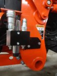
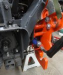
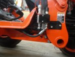
Next up is the 3rd function valve assembly, bracket and designated mounting location. Let’s get it assembled, mounted, and start getting some hoses hooked up. You’ll see some pics showing the following: The clearly marked ports A&B, their adapters and quick couplers. And mounted with its bracket on the front right loader post. I use the same mounting holes for another bracket that the front corner of my home made removeable cab sits on. I was a little worried that my cab’s front corner bracket would require alteration to accommodate the 3rd function valve assembly. Not to worry. In fact, the plate that the cab rests on actually protects the top of the small relays that get plugged into the valve. For everyone else in a normal situation access to those relays would be a little easier.
A and B Port Fittings.jpg

A and B Ports.jpg

Loader Post Mounting.jpg

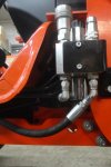
This pic showing the P & T port hose connections (bottom of block) is where I deviated a little from the kit’s instructions.
PB and T Hoses.jpg

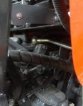
Those instructions say that the P & T hoses connect directly to the supplied adapters only. That would mean those hoses would go straight down before curving back towards the tractors PB and T ports. Trying that left fairly large downward loops that were well below the tractor’s main frame. But remember my backhoe hookups were partially done already? That left me with a 90 degree elbow unused. Putting that elbow on the Summit valve’s T port cleaned up one downward loop nicely. I purchased a 45 degree elbow for the P port (90 degrees would not work) and was able to keep both hoses routed and secured well above the bottom edge of the tractor’s frame. An “S curve” was needed in the hose leading back to the backhoe adapter bracket in order to use up some extra length. Normally (without a backhoe) that hose would rout to the top of the rear housing and into the 3 pt. hitch port. At some point (depending on cost) I may have that same hose shortened and have a new end put on. But for now, it should work as is. If you didn’t have a backhoe attachment and wanted to run your hoses like this, you would need to purchase and extra 90 and 45 degree elbow.

The last pic (below, top view) illustrates how close in the assembly sits next to the loader post. It’s well within the wheel base. Still, I think I’ll make a guard for the assembly that would use the same mounting holes. Just in case a sapling snaps back while doing some brushing. But more likely to prevent an operator error that could cause a branch to try to wedge between the loader post and valve causing havoc.
Top View.jpg

Next up: Let's get the hose that runs from the "T" port back to the backhoe hydraulic input quick coupler. (If you don't have the backhoe this hose would rout back to the 3 pt. hitch port. Remember, that's the other end of that piping removed at the very start. The kit supplies an adapter and a 90 degree fitting for the new hose install.)

Stay tuned. Back soon. and thanks for lookin' !
All comments and suggestions appreciated.

David
 
  • Like
Reactions: 1 user

bird dogger

Well-known member
Vendor Member

Equipment
Kubota B2650 and lots of other equipment
Feb 24, 2019
1,625
1,509
113
North Dakota
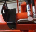
Now to finish installing/bolting the backhoe quick couplers in place. These pics show the following: the same hole location where the original pipe bracket (removed) was bolted to. (the new bracket mounts to the inside of the backhoe subframe.) The hose coming from the Summit valve T port gets connected to the new adapter/bracket and the original quick coupler. And finally, the hoses all made up and bracket bolted in place. Don’t forget to put those hose caps over the hose before you attach the quick couplers!! :eek:
Backhoe Fitting Location.jpg

Backhoe to Valve T Port.jpg

Backhoe New Rear Hookups.jpg

Backhoe Hookups Installed.jpg

At this point you could actually use your tractor again as you've completed your hydraulic loop circuit from the PB to the Summit valve and back to the tractor's tank through the backhoe or the 3 pt. hitch depending on your situation. If you have tools ready to go, a clean table top to work from, and the right parts laid out.....the process up to now could be done in a few hours or less. And the tractor is now back in service....just not 3rd function ready.
More to follow!

Next up: Loader bracket, front quick couplers, hoses
 
  • Like
Reactions: 1 user

Bill Groom

Member

Equipment
B7100 HST
Apr 2, 2019
115
0
16
N.E. Ohio
Very informative, and great pics. Thank you for this. While it is not a quick process, the saved labor costs allows another implement to be added. And may I say, well done!

Sent from my SM-N976V using Tapatalk
 

bird dogger

Well-known member
Vendor Member

Equipment
Kubota B2650 and lots of other equipment
Feb 24, 2019
1,625
1,509
113
North Dakota
Very informative, and great pics. Thank you for this. While it is not a quick process, the saved labor costs allows another implement to be added. And may I say, well done!

Sent from my SM-N976V using Tapatalk
Hi Bill. First, thanks for the compliments. Second...Your more than welcome!! Thirdly....the process really is pretty quick. It's already done. If one is set up with a block of time and prepared in advance this is really an easy afternoon project. The info is out there but in bits and pieces that took me a while to figure out and decide to tackle this because the more you understand the easier it is.

I thought it would be great to take some detailed pics along the way. Putting them together in a logical order that makes sense should take some of the mystery out. It's something most anybody could tackle on their own. (Some tools and basic skills necessary) :D

It's taking much more time to write things up, downsize some pics and organize them than it did to do the install. But if it helps somebody down the road it'll be well worthwhile.

More to come very shortly. Stay tuned, Bill.

Best regards,
David
 
  • Like
Reactions: 1 user

bird dogger

Well-known member
Vendor Member

Equipment
Kubota B2650 and lots of other equipment
Feb 24, 2019
1,625
1,509
113
North Dakota
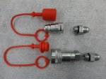
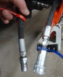
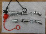
The loader cross tube bracket is attached using an existing bolt/location. With the pieces laid out showing the adapters, locknuts, etc., attaching all to the loader bracket is pretty self-explanatory. Since the quick couplers use an O-ring fitting it’s an easy change to swap things vs. gooped up NPT fittings. I also use an O-ring grease to lightly lubricate all the O-rings during the final assembly throughout the kit.
Front End QC Components.jpg
Loader Hookup Mounting Bracket.jpg

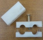
With hoses attached the instructions say to use the included tie wraps to secure them in place. Those tie wraps are pretty skimpy to go around the loader cylinders let alone the loader arm. To keep the hoses securely in place at the front of the loader I made a dual hose clamp from some scrap HDPE.
Fabricated Hose Spacer Block.jpg
Front Couplers Assembled.jpg
And, YES, I drilled and tapped a ¼-20 hole in the loader arm to secure it in place. :eek:! :D The tapped hole is above all the hydraulic piping. And actually, that hollow area of the loader arm is open to the atmosphere at the extreme bucket end of the arm. Some thread locker seals the tapped hole anyway. Two matching holes at each end with 1/16 inch pins keeps the HDPE clamp pieces from twisting out of line once bolted in place.

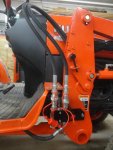
The last pic shows the front hoses routed through the loader post hose guide and coupled to the 3rd function A & B ports. Some hose protector sleeve material is on order to be installed over all hoses. I’m hoping that will protect these where they pass through that guide and might help them to slip and slide as they flex a little with the loader raising and lowering. The hose routing may be a work in progress to find the best solution.
Port A and B Hoses.jpg

All the hydraulic hose work is now done so it’s time to get the control parts together and ready for power.
 
Last edited:
  • Like
Reactions: 1 user

bird dogger

Well-known member
Vendor Member

Equipment
Kubota B2650 and lots of other equipment
Feb 24, 2019
1,625
1,509
113
North Dakota
Getting the controls installed and hooked up is even easier than the kit’s instructions state because they’re all pre wired using two multi pin connectors. The wiring was updated but not the instructions. Only two wires are left for you to decide how you want to power the system. A red wire to 12v DC+ and a black wire to 12v DC-. The joystick handle is pre wired and the same for the control relays. I picked a spot to route the cable up under the seat area where the multi pin connector connects to the joystick cable. I chose (for now) to have that connection there instead of wrapped up somewhere underneath where it can’t be seen or has a chance of getting snagged by the brush gremlins.
Joystick Control and Relays.jpg
Control Wiring.jpg

The control relays are plugged in and then held in place on the electric control valve with screws down the relay’s center.
Valve Relays Installed.jpg

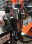
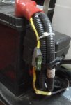
And this is what it looks like mounted. My cab bracket is off at the moment for a mod which will support my power supply hookups. You can see the red and black power leads dangling loose underneath the loader post. If you look closely you can also see the control cable to the loader joystick zip tied to the hydraulic piping running back to the loader valve.
Valve Controls Mounted.jpg

If you’ve been waiting for the difficult part of the control hookup you’re out of luck. :( There is none!! Other than bringing power to the 3rd function system the control work is basically done.

Next up will be mounting the joystick handle to the loader’s control arm and deciding how to bring power to the 3rd function system.
 
  • Like
Reactions: 1 user

bird dogger

Well-known member
Vendor Member

Equipment
Kubota B2650 and lots of other equipment
Feb 24, 2019
1,625
1,509
113
North Dakota
The joystick handle has some removeable bushings to size it to your loader joystick. You can turn it to face any direction you want. It’s suggested you have the buttons face the operator. 4 screws tighten it down securely.
Joystick Bushings.jpg Joystick Controller.jpg

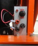
Here’s my power supply parts I scrounged out of my parts bins. The ability to switch the system on/off as needed rather than have it automatically on when the tractor is running would eliminate unnecessary on time when the grapple wasn’t being used. A switch and indicator light will take care of that.
My Power Panel Components.jpg

My cab heater and blower fan is also in the front right corner. My power supply hookup will serve to power that in the winter too. Here’s a pic or two of that in progress:
Auxilliary Power Panel.jpg Auxilliary Power 12 VDC.jpg

I plan to devise a little cover to fit over the top of the mounting to shed rain and keep the component’s back sides as dry as possible.

The black and red power leads shown are the same leads in the kit. The red lead has its own fuse (blue fuse holder) protecting the Summit 3rd Function system. I can size the other fuse to protect whatever else is hooked up to the front terminals. They’ll also be handy to power the electric pump on the 3 pt. boom sprayer.

So how is this little distribution block powered up? That’s coming up in the next episode. Stay tuned and thanks for lookin’ !! :)

David
 
  • Like
Reactions: 1 user

B737

Well-known member
Lifetime Member

Equipment
LX3310
Jun 9, 2019
2,024
2,200
113
USA
Dave do you feel any difference with the extra few inches added to the joystick length? I may carefully cut ~2" off the joystick end so the controller is the same distance the rubber knob used to be. My body was used to that feel.
 

bird dogger

Well-known member
Vendor Member

Equipment
Kubota B2650 and lots of other equipment
Feb 24, 2019
1,625
1,509
113
North Dakota
Dave do you feel any difference with the extra few inches added to the joystick length? I may carefully cut ~2" off the joystick end so the controller is the same distance the rubber knob used to be. My body was used to that feel.
It does seem a little higher up. More noticeable to me was the different feel with the lager knob due to housing the switches internally. That'll probably be the new normal after a while I suspect.

B737, your suggestion is sure a simple fix (I hadn't thought about) to lower the height! Now I'll have to keep that in mind after some time on the loader.

When pricing out some individual components I had looked at some other handles that seemed more ergonomic but their price was too high for me. If I can find them again I'll post some links to them later.

Thanks for the great suggestion.

david

Edit: I went out and took this pic later. On the B2650 the new handle lines up quite nicely with the arm rest and really is already at a nice comfortable height as is. Probably won't need any height adjustment at all. Who'd have guessed that would be the case?:D
New Control Handle Height.jpg
 
Last edited:
  • Like
Reactions: 1 user

bird dogger

Well-known member
Vendor Member

Equipment
Kubota B2650 and lots of other equipment
Feb 24, 2019
1,625
1,509
113
North Dakota
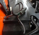
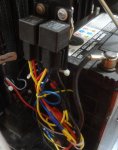
To provide some auxiliary power hookups for my cab, sprayer, etc. I had previously mounted a couple of 12v DC auto relays under the hood near the battery. Only one was needed but since they're cheap two were mounted on a bracket with one being a spare. The relay coils are energized when the tractor is running. The relay input contacts get 12v DC+ from the battery through a fused wire connected at the + battery post. The output contacts have an auto fuse holder connected to the wire pigtails. At some point I'll figure out how to mount a terminal block in that location to clean up the wiring.
12 vdc Auto Relays.jpg Auto Relay DC Fused Supply.jpg

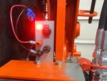
A pair of red and black wires connects to the auto fuse holder and battery ground and was run through a piece of vinyl tubing over to my power block for the 3rd function. Here's what that block looks like when powered up with the switch on. That red LED glows pretty bright. It's an easy reach down to operate the switch from the tractor seat. The switch only need be a single pole-single throw (SPST) but the nice label was found on a double throw, center off switch so that's what was used.
Power Panel_ON.jpg

This last pic shows an internal indication light turned on in the valve relay when the related button is pressed on the joystick control handle. You can either look, listen or feel for the valves to operate when those buttons are pressed. That little indicator light will be a nice feature for trouble shooting when needed!
Valve Relay Energized.jpg


There was no mention of these relays in the kit's instructions. It was obvious where they went. They're also interchangeable with each other. If you want to change what button opens or closes your grapple you could either swap relay positions or your hoses. (My thoughts, anyway.) Afterwards, I did find a different instruction guide online that did mention those relays. One interesting point mentioned is that the top of the solenoids when mounted should not contact any metal. I'm guessing that would somehow affect their ability to operate the valves within the assembly.

So, there you have it. Installation complete! Mission accomplished. All in all, the kit is nicely put together and turned out to be a fairly easy install. No black magic or crystal ball needed. With only a few proper tools it can easily be done in your shop, garage, or anywhere you can keep things clean while you tap into your hydraulic system. All with very minimal down time!

Next up: Fabricating some protection for the lower valve components.
 
Last edited:
  • Like
Reactions: 1 user

bird dogger

Well-known member
Vendor Member

Equipment
Kubota B2650 and lots of other equipment
Feb 24, 2019
1,625
1,509
113
North Dakota
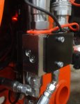
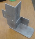
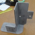
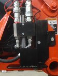
Here's the valve protector that I cobbled together from some cutoffs from another project. 3" angle pieces and a flat welded across the bottom with a bolt pattern to mount with the same two bolts holding everything else together. It's pretty stout. Better to take the time and put it on now rather than wish you had later. It's nothing fancy but should do the job helping to protect the parts you can't readily see while sitting on the seat.
Valve Guard Inward.jpg

Valve Guard Outward.jpg

Valve Protection Installed.jpg


Now, what was that "Speed Bump" about mentioned in Post #6? It involved something I noticed when sorting the pics for posting. More on that coming soon.....
 
Last edited:

bird dogger

Well-known member
Vendor Member

Equipment
Kubota B2650 and lots of other equipment
Feb 24, 2019
1,625
1,509
113
North Dakota
Different 3rd function kits, options and components were considered before purchasing the Summit kit specific for the B2650/B3350. I was interested in Everything Attachments grapple so I started my search there. They use the WR Long valve and I was referred to Josh (at WR Long) for some answers to my questions. Unable to answer any specific questions about the B2650 system, Josh was adamant that the 3rd function valve was to be installed directly after the loader valve's power beyond port and before any backhoe or other hydraulic attachments. I understood it to be because of potential back pressures and possible seal blowout. I'm still not sure if that made sense or not. But that kit was higher priced than others and maybe not Kubota B2650 specific with the backhoe attachment.

Summit Hydraulics offers kits made for the B2650/3350, a more universal kit, and some that only include the valve, controls and a few fittings (you supply mounts, hoses, etc.). One difference between the valves is in how they can be plumbed into your tractor's hydraulics. When I spoke with Patrick and asked about my situation (with a backhoe) he said either type would work. Their B2650 kit was model specific, the others not. The B2650 kit's valve block would be a cleaner install with the hose layout. The universal kit could be plumbed a little differently with a backhoe option on the tractor. Questioned again about the difference in plumbing, Patrick said either would work for me.

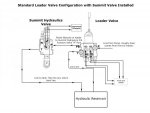
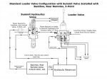
Here's the install diagrams for the two different valves (found on their website):
3rd-function-valve-Configuration-without-backhoe-600x450.jpg This B2650 kit is plumbed in like this first diagram with the Valve T port going to the backhoe input and the backhoe return line feeding the 3 pt hitch and then to hydraulic (tank) reservoir.

Summit Universal 3rd Function with Backhoe.jpg Notice the use of the optional N Port to feed the backhoe or a different hydraulic attachment with this universal valve.

In the end, Summit's B2650 3rd Function Kit (TFK7) was ordered. Here's some specs from their website listed for that model: Valve Body Features Max Operating Pressures: (Ports) P=5080 PSI T=3050 PSI A&B=5080 PSI 3000 PSI RATED

Here's that speedbump: After the install and getting pictures ready for this thread, I noticed this picture of the valve's data plate. Do you notice what I did? Pay attention to the port max pressure ratings.
Summit Valve Data.jpg

Oh CRAP! I called and spoke with Patrick again and told him of the discrepancy between their website and the data plate info. Strange, he said, that data plate must have a misprint. (I didn't find that very plausible). Asked if their valve was going to cause me trouble in my situation, Patrick assured me it was not. He said a large number of them have been installed with backhoes and none had problems. I was not to worry. What to do??? Since Summit says not to worry, I'll go with it as is and see what happens.

If you haven't spotted the discrepancy yet, compare the Max T Port pressure rating listed on their website (see above) versus the T port rating on the valve data plate. (data plate: T=1450 PSI) That's quite a difference. And much less than the B2650 max hydraulic pressure. Maybe there's such a safety factor built in that in this case it doesn't matter? But their website disagrees with their product's stated pressure rating. And nowhere on their website does it say that this kit is not to be used when a backhoe is installed.

The WR Long FAQs state to install their valve exactly the same as this Summit valve. See question #6 (the 2nd #5 :D)
https://www.wrlonginc.com/help

And even more strange, Messick's Land Pride instructions:
https://www.messicks.com/part/380-168a/b2650-b3350-third-function-valve-kit
(see install Instructions pdf) are exactly the same as Summit's except for the brand name on the instruction sheet. Even the pics in both are the same photo copied pics and almost verbatim instructions to follow.

Summit gladly emailed me pdf copies of their install instructions prior to the purchase.

I couldn't find a pdf of the WR Long instructions to see if they were identical. Chances are they could be, too.

In the end, maybe all is well. The Summit kit was easy to install, complete, and even worked when installed with a backhoe attachment. They could've included a couple LARGE tie wraps to secure the hoses on the loader arm itself but I like my homemade clamp better anyway. No biggie!

All the 3rd function systems that I could find for my situation on the compact tractor apparently use the same style with the simpler plumbing. Do the D03 subplate type valves have T ports rated for full tractor hydraulic pressures? Perhaps the hydraulic gurus reading this can comment on and explain the T port discrepancy and the reason for the two different valve styles???

The grapple arrives shortly but it might be a while til things dry up enough to use it. Until then, fingers crossed. :confused:
 
Last edited:
  • Like
Reactions: 1 user