I will try to double check the transmission machining for flatness but it's hard to get in there so will see. Beyond that it'll be later next week before I attempt to put it back together. Thanks for all the grear help!Exactly. That gives you a direct measurement and eliminates a lot of error. Oring is probably 2mm (.079) and thst should seal fine if the two surfaces are flat.
Dan
Hydraulic Relief Valve Adjustment
- Thread starter trynfixit
- Start date
I hate to admit defeat (by inanimate objects) as much as anybody, but at this stage I'd put the plate back on and plumb her up to the loader PB, or vice versa.
Trynfixit, you don't happen to have the WSM so you could attach the hydraulic diagram, do you?
Trynfixit, you don't happen to have the WSM so you could attach the hydraulic diagram, do you?
TheOldHokie
Well-known member
Lifetime Member
Equipment
L3901/LA525, B7200DT/B1630, G2160/RCK60, G2460/RCK60
I could not findva WSM.I hate to admit defeat (by inanimate objects) as much as anybody, but at this stage I'd put the plate back on and plumb her up to the loader PB, or vice versa.
Trynfixit, you don't happen to have the WSM so you could attach the hydraulic diagram, do you?
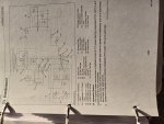
If you look at the parts diagrams things appear pretty obvious. The pump delivers oil into the top of the lift cover via a long pipe and the system relief valve is right below that connection
The loader outlet block is on the pump end of the delivery pipe and has.a pressure out and pressure return connection. Consequently the loader valve has its own relief and a third tank return.
The rear outlets are just below the system relief and presumably protected by both the system relief and the loader relief.
Dan

This one?I hate to admit defeat (by inanimate objects) as much as anybody, but at this stage I'd put the plate back on and plumb her up to the loader PB, or vice versa.
Trynfixit, you don't happen to have the WSM so you could attach the hydraulic diagram, do you?
Attachments
-
 782.1 KB Views: 6
TheOldHokie
Well-known member
Lifetime Member
Equipment
L3901/LA525, B7200DT/B1630, G2160/RCK60, G2460/RCK60
Bingo.This one?
Items 11, 12, 13, 14. and 15 are the hydraulic circuit you are dealing with.
Notice that the two outlet blocks are simply daisy chained together. Connecting your valve at the front block is functionally equivalemt to connecting it at the rear block.
Dan
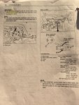
This is the instruction page I found in the operator manual section. It is a better one than came with the RH Outlet Block.This one?
Attachments
-
 921.6 KB Views: 6
TheOldHokie
Well-known member
Lifetime Member
Equipment
L3901/LA525, B7200DT/B1630, G2160/RCK60, G2460/RCK60
Yes. KUBOTA has been using that same setup on many different models for 40 plus years.This is the instruction page I found in the operator manual section. It is a better one than came with the RH Outlet Block.
Dan
Yes I see that.Bingo.
Items 11, 12, 13, 14. and 15 are the hydraulic circuit you are dealing with.
Notice that the two outlet blocks are simply daisy chained together. Connecting your valve at the front block is functionally equivalemt to connecting it at the rear block.
Dan
Thanks. The manual explains it well. The front block is before the tractor's relief valve and the rear block is after. Does your loader's T line tie into that return port or somewhere else?This is the instruction page I found in the operator manual section. It is a better one than came with the RH Outlet Block.
I'm not positive, will have to look tomorrow.Thanks. The manual explains it well. The front block is before the tractor's relief valve and the rear block is after. Does your loader's T line tie into that return port or somewhere else?