Ok, thanks! I'm wondering why the Kubota drawing and instructions I found on their website said to use all three ports, which got me confused in the first place, but I'm going to look at changing from T to PB. As you say, still have to fix leak.Using power beyond is the proper way to connect that valve and it will work perfectly if correctly plumbed.
If Summit told you to use the tank port they did not understand your situation. You probably told them the port on the tractor is a return to tank which it is not. It is high pressure carry over (power beyond) for the 3pt and will see full system pressure. The tank port on Summit's valve is rated for a maximum of 725 PSI.
None of that has anything to do with your leak problem.
Dan
Hydraulic Relief Valve Adjustment
- Thread starter trynfixit
- Start date
TheOldHokie
Well-known member
Lifetime Member
Equipment
L3901/LA525, B7200DT/B1630, G2160/RCK60, G2460/RCK60
You will need the power beyond sleeve for your valve.Ok, thanks! I'm wondering why the Kubota drawing and instructions I found on their website said to use all three ports, which got me confused in the first place, but I'm going to look at changing from T to PB. As you say, still have to fix leak.
Dan

Ok, starting to make sense, I appreciate your knowledge. I didnt ask because i didn't know where or who to ask so went back to the sellers. I do have the sleeve for the N port, etc. But I still don't know which is the T port on the tranny. Is that the "Plug" right next to the RHO block? I had wondered about that. I may try to fix this leak first, less work now maybe. But sounds like the other way would be better.Had ypu asked I would have told you to daisy chain off the loader valve. Its more accessible and less expensive.
To properly plumb your valve you would need to first install the power beyond sleeve in the N port. Then connect that sleeve to the inlet port on the hydraulic outlet block. You must also connect the T port on the valve to a direct tank return on the tractor. Without it nothing hooked to your valve will work.
Again none of this is related to the leak. So what do youbwant to fix?
Dan
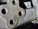
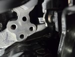
Yes that is my block. Yes the oil seeps from between the block and the transmission case. I don't see any anywhere else at this point.Here is your block.
View attachment 132628
According to Messicks it fits 47 very different models. i am quite sure the number in your instructuons is not the maximum pressure rating of the block itself. Its probably the system pressure of one of those dufferent models chosen at random by some clueless document author.
So back to your problem. Are you positive its leaking at the orings?
Dan
TheOldHokie
Well-known member
Lifetime Member
Equipment
L3901/LA525, B7200DT/B1630, G2160/RCK60, G2460/RCK60
The plug in the side of the transmission is a tank return. It is not threaded and intended for use with the special pipe that comes with the OEM remote valve stack. Using it for your valve becomes an issue of how to make a connection to it.Ok, starting to make sense, I appreciate your knowledge. I didnt ask because i didn't know where or who to ask so went back to the sellers. I do have the sleeve for the N port, etc. But I still don't know which is the T port on the tranny. Is that the "Plug" right next to the RHO block? I had wondered about that. I may try to fix this leak first, less work now maybe. But sounds like the other way would be better.
Dan
Yes, thanks. I figured out where that is, under a little strap. I'll check to see if I can buy that rubber hose or get it's specs. It must be zero pressure or very low. Looking at it I think it's doable to change ports to get the valve correct. I am attempting to analyze the leak problem first. Thanks again for all the help! I'll post when I get it to work, or when I have more questions : )The plug in the side of the transmission is a tank return. It is not threaded and intended for use with the special pipe that comes with the OEM remote valve stack. Using it for your valve becomes an issue of how to make a connection to it.
Dan
Also, if I can't get the leak answered I may just skip it and go to the PB circuit. I can't keep fighting the leak, tractor in shop gets no work done. Have it good!Yes, thanks. I figured out where that is, under a little strap. I'll check to see if I can buy that rubber hose or get it's specs. It must be zero pressure or very low. Looking at it I think it's doable to change ports to get the valve correct. I am attempting to analyze the leak problem first. Thanks again for all the help! I'll post when I get it to work, or when I have more questions : )
TheOldHokie
Well-known member
Lifetime Member
Equipment
L3901/LA525, B7200DT/B1630, G2160/RCK60, G2460/RCK60
The pipe has a groove on the OD that holds an oring. The pipe and oring are a friction fit in the hole in the case. It sees minimal (100 PSI) pressure but there is nothing to hold it in place. Most people simply give up on using it and run the tank line to the front hydraulic block where they install a tee on the loader tank retirn connection.Yes, thanks. I figured out where that is, under a little strap. I'll check to see if I can buy that rubber hose or get it's specs. It must be zero pressure or very low. Looking at it I think it's doable to change ports to get the valve correct. I am attempting to analyze the leak problem first. Thanks again for all the help! I'll post when I get it to work, or when I have more questions : )
Dan
Interesting. Thanks for the heads up on that. (This got way long. I know you have stuff to do besides read my explanations so if you dot feel like it i understand. You've already helped as have others here, thanks!)The pipe has a groove on the OD that holds an oring. The pipe and oring are a friction fit in the hole in the case. It sees minimal (100 PSI) pressure but there is nothing to hold it in place. Most people simply give up on using it and run the tank line to the front hydraulic block where they install a tee on the loader tank retirn connection.
Dan
I originally had the T port tee'd into the PB fitting the goes from the FEL valve to the transmission. I misunderstood from a kubota drawing. Now I think that would be the hose that should feed the P port on my valve then N back to that port on the transmission. T would have to do as you said, connect to the hose or go back to the tank line off the FEL valve.
I am wondering if there would be any difference in performance doing it that way, the lines are bigger, wondering if the flow is less restricted so everything run a little cooler? Works fine as is, just wondering if one better than the other.
I tried to determine if there is any irregularities in the casting, without much success tho there seemed to be a small flaw in the top side of the lower port. So I did some careful polishing, see b4vand after pics attached. It's tough to get in there so I think it's as good as it's going to be. I still could do a test for uneveness in the machining with Dykem Blue but I dont have any at the moment.
I came across a page in the Operators Manual (not in my WSM) that shows the same setup for the Rear Hydraulic Outlet Block but with max pressure ratings up where the B3000 normally runs, above 2300 psi. So you and others here are correct, the pressure is not the problem. Not that I questioned whether you were right. I did question the spec on the sheet and as you said that must have been a sheet for a different tractor. Came with the block.
The blank cover that was on the outlet ports uses an elongated "O ring" that covers both ports. So the fact that it did not leak before I installed the block is understandable.
If you think there would be no difference in performance, run cooler or whatever, going without the RH Outlet block and using PB from the FEL valve, the I will try the block again. I still have to deal with N and T proper plumbing. Thanks again for any and all advice!
Attachments
-
 576.6 KB Views: 14
 -
 357.9 KB Views: 15
TheOldHokie
Well-known member
Lifetime Member
Equipment
L3901/LA525, B7200DT/B1630, G2160/RCK60, G2460/RCK60
To daisy chain the new valve off the loader:Interesting. Thanks for the heads up on that. (This got way long. I know you have stuff to do besides read my explanations so if you dot feel like it i understand. You've already helped as have others here, thanks!)
I originally had the T port tee'd into the PB fitting the goes from the FEL valve to the transmission. I misunderstood from a kubota drawing. Now I think that would be the hose that should feed the P port on my valve then N back to that port on the transmission. T would have to do as you said, connect to the hose or go back to the tank line off the FEL valve.
I am wondering if there would be any difference in performance doing it that way, the lines are bigger, wondering if the flow is less restricted so everything run a little cooler? Works fine as is, just wondering if one better than the other.
I tried to determine if there is any irregularities in the casting, without much success tho there seemed to be a small flaw in the top side of the lower port. So I did some careful polishing, see b4vand after pics attached. It's tough to get in there so I think it's as good as it's going to be. I still could do a test for uneveness in the machining with Dykem Blue but I dont have any at the moment.
I came across a page in the Operators Manual (not in my WSM) that shows the same setup for the Rear Hydraulic Outlet Block but with max pressure ratings up where the B3000 normally runs, above 2300 psi. So you and others here are correct, the pressure is not the problem. Not that I questioned whether you were right. I did question the spec on the sheet and as you said that must have been a sheet for a different tractor. Came with the block.
The blank cover that was on the outlet ports uses an elongated "O ring" that covers both ports. So the fact that it did not leak before I installed the block is understandable.
If you think there would be no difference in performance, run cooler or whatever, going without the RH Outlet block and using PB from the FEL valve, the I will try the block again. I still have to deal with N and T proper plumbing. Thanks again for any and all advice!
1) Disconnect the power beyond hose at the front hydraulic block and connect it to P on the new valve.
2) Connect the N port on the new valve to the port on the hydraulic block.
3) Install a tee in the loader tank return hose and connect it to the T port on the new valve.
Thats it.
Two orings in the new outlet versus one in the old one makes no difference. They are holding the same pressure
Dan
Last edited:
Thanks much! Re o rings I understand, what I meant was the tiny flaw on the lower port (if that's the problem) would be inside the o ring and not under it because of its location. No matter. Much obliged for al the help! I'm learning.To daisy chain the new valve off the loader:
1) Disconnect the power beyond hose at the front hydraulic block and connect it to P on the new valve.
2) Connect the N port on the new valve to the port on the hydraulic block.
3) Install a tee in the loader tank return hose and connect it to the T port on the new valve.
Thats it.
Two orings in the new outlet versus one in the old one makes no difference. They are holding the same pressure
Dan
TheOldHokie
Well-known member
Lifetime Member
Equipment
L3901/LA525, B7200DT/B1630, G2160/RCK60, G2460/RCK60
You are learning.Thanks much! Re o rings I understand, what I meant was the tiny flaw on the lower port (if that's the problem) would be inside the o ring and not under it because of its location. No matter. Much obliged for al the help! I'm learning.
My gut feeling is one or possibly both of the counterbores that hold the o-rings in the rear hydraulic block are cut too deep and you are not getting enough "squeeze" to make a good seal. I would check that using a straight edge and feeler gauges to measure the protrusion as I mentioned earlier.
Rule of thumb for a static face seal like this is about 20%-30% compression. For example on a 2.5 mm thick oring thats .5 to .75 mm (.020"-.030") protrusion.
Dan
Last edited:
T
ThanksYou are learning.
My gut feeling is one or possibly both of the counterbores that hold the o-rings in the rear hydraulic block are cut too deep and you are not getting enough "squeeze" to make a good seal. I would check that using a straight edge and feeler gauges to measure the protrusion as I mentioned earlier.
Rule of thumb for a static face seal like this is about 20%-30% compression. For example on a 2.5 mm thick oring thats .5 to .75 mm (.020"-.030") protrusion.
Dan
Thanks yet again. Makes good sense. I have a mic caliper for a start. Also feeler gauges, will do some checking.You are learning.
My gut feeling is one or possibly both of the counterbores that hold the o-rings in the rear hydraulic block are cut too deep and you are not getting enough "squeeze" to make a good seal. I would check that using a straight edge and feeler gauges to measure the protrusion as I mentioned earlier.
Rule of thumb for a static face seal like this is about 20%-30% compression. For example on a 2.5 mm thick oring thats .5 to .75 mm (.020"-.030") protrusion.
Dan
Well with what I have to measure with the counterbores seem to be pretty consistent between .053 and .054. The O rings do vary a little but thickest seems .075 and thinest .072. Not sure I'm real accurate but if that is true I'm at about 27% protrusion. I will do some more measurements and if I go that route will see if I can find two O rings at .075. The variation is with the two new ones I have left. Could order some more I guess. Thanks for your "gut" wisdom on this. I'm thinking it has something to do with that. I've been careful in torquing the bolts evenly. Book says about 18 to 22 lb ft for an M8 grade 7. Thanks much!T
Thanks
Thanks yet again. Makes good sense. I have a mic caliper for a start. Also feeler gauges, will do some checking.
TheOldHokie
Well-known member
Lifetime Member
Equipment
L3901/LA525, B7200DT/B1630, G2160/RCK60, G2460/RCK60
Ditch those instruments. All you want to knpw is the height of the oring above the face. Lay a good straight edge across the oring and use feeler gauges to measure the gap between the straight edge and the face of the block. Do each oring individually.Well with what I have to measure with the counterbores seem to be pretty consistent between .053 and .054. The O rings do vary a little but thickest seems .075 and thinest .072. Not sure I'm real accurate but if that is true I'm at about 27% protrusion. I will do some more measurements and if I go that route will see if I can find two O rings at .075. The variation is with the two new ones I have left. Could order some more I guess. Thanks for your "gut" wisdom on this. I'm thinking it has something to do with that. I've been careful in torquing the bolts evenly. Book says about 18 to 22 lb ft for an M8 grade 7. Thanks much!
Dan
Guess I'll be on hold for couple weeks waiting for the return pipe. Will post results later. Thanks all!Well with what I have to measure with the counterbores seem to be pretty consistent between .053 and .054. The O rings do vary a little but thickest seems .075 and thinest .072. Not sure I'm real accurate but if that is true I'm at about 27% protrusion. I will do some more measurements and if I go that route will see if I can find two O rings at .075. The variation is with the two new ones I have left. Could order some more I guess. Thanks for your "gut" wisdom on this. I'm thinking it has something to do with that. I've been careful in torquing the bolts evenly. Book says about 18 to 22 lb ft for an M8 grade 7. Thanks much!
OkDitch those instruments. All you want to knpw is the height of the oring above the face. Lay a good straight edge across the oring and use feeler gauges to measure the gap between the straight edge and the face of the block. Do each oring individually.
Dan
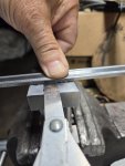
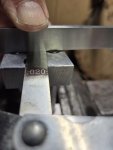
Something like this? .020 and if the o ring thickness is .074 then it's 27% protruded. Hard to hold the straightedge on the individual o rings. Did that with a machinist rule and seemed there might be a thousandth difference measured 90 deg apart. .018 and .017
Attachments
-
 321.8 KB Views: 11
Something like this? .020 and if the o ring thickness is .074 then it's 27% protruded. Hard to hold the straightedge on the individual o rings. Did that with a machinist rule and seemed there might be a thousandth difference measured 90 deg apart. .018 and .017
Attachments
-
 260.4 KB Views: 5
TheOldHokie
Well-known member
Lifetime Member
Equipment
L3901/LA525, B7200DT/B1630, G2160/RCK60, G2460/RCK60
Exactly. That gives you a direct measurement and eliminates a lot of error. Oring is probably 2mm (.079) and thst should seal fine if the two surfaces are flat.Something like this? .020 and if the o ring thickness is .074 then it's 27% protruded. Hard to hold the straightedge on the individual o rings. Did that with a machinist rule and seemed there might be a thousandth difference measured 90 deg apart. .018 and .017
Dan