New old tools

Runs With Scissors

Well-known member

Equipment
L2501 TLB , Grappel, Brush Hog, Box Blade, Ballast box, Forks, Tiller, PH digger
Jan 25, 2023
4,165
5,612
113
Michigan
Hey, you gotta do what you gotta do with what you have. I've seen people disassemble machinery and lay planks and ropes down staircases to get it in or out of a basement workshop. Your operation looks pretty straightforward.
;)
 

Runs With Scissors

Well-known member

Equipment
L2501 TLB , Grappel, Brush Hog, Box Blade, Ballast box, Forks, Tiller, PH digger
Jan 25, 2023
4,165
5,612
113
Michigan
I've started having a play with the new lathe - finding little things that need sorting out.

Here's a few specs:

Motor - Chinese 3 HP single phase reversible.
Diameter over bed - 360 mm (14").
Diameter over gap - 600 mm (24").
Headstock bore - 40 mm (1.5" plus a bit).
Bed length - 1660 mm (65").
Between centres - 1380 mm (54").
Weight - a lot.
Slowest speed as is - 40 rpm with back gears
Auto feed - forward and reverse saddle and cross slide.
Screw cutting - metric and imperial.
4 jaw chuck - 300 mm (12").
3 jaw chuck - 260 mm (10.5") Taylor conical/tapered scroll chuck with reversing jaws (I'm told they were the Rolls Royce of chucks in their day - I think their day was 60 years ago) - only grips down to 16 mm DIA.
Faceplate diameter - 400 mm (16").
Steadies x 2 - fixed and travelling.

There's also a whole bunch of tools, a few drill bits, a good 3MT drill chuck, several Morse taper adaptors, a coolant pump. Fit no extra charge there's some dodgy wiring and no emergency stops, no guards over belts - these will be addressed.

Pretty happy with the purchase.

Here's a video showing the operation with back gears engaged - I made this for the gentleman I bought lathe off. He had never used a lathe when he bought it and didn't know what back gears were. He asked if I could keep him updated with it's progress as I get it up and running. He lives fairly close so he'll probably drop in to have a look too.

Feel free to correct me on anything I've messed up here - as I've said before, I'm no machinist, just a retired engineer trying really hard.


One problem was the pin that engages and disengages the chuck shaft to the pulley shaft. With the pin pushed in the two shafts are locked together and you get three "high" speeds dictated by the flat pulleys. With the pin pulled out the two shafts can spin independently - this allows the back gears to be engaged to get really low speeds.

The problem with the engage/disengage pin was that it's top end was broken off so it wouldn't hold in position properly. The next problem was that it couldn't be removed as it hit the casting behind the chuck - I didn't really want to disassemble the main shaft just for this. Serviceability obviously want on the list of requirements when the lathe was designed.

The original pin was all one-piece and looked like this - 16 mm DIA x 40 mm, 8 mm DIA x 65 mm.

View attachment 181265

There's no way to get it into or out of the hole it goes in as it's too long. To get the original pin out I had to gradually cut bits off until it was short enough to come out, then it was too short to do the job.

View attachment 181266

I decided to make a new pin in two pieces. The larger diameter piece with a M8 thread through the middle, and a cut off M8 bolt that screwed into it.

Screwed together with the same dimensions as the original pin, there's no way it's going in the hole.

View attachment 181267

But pulled apart, I could push the larger diameter section into the hole....

View attachment 181271

View attachment 181268

The hex key is in a small hole in the 16 mm diameter piece. It's there so I can stop it turning while I screw the cut-off M8 bolt into it.

View attachment 181269

Then I could screw in the cut off M8 bolt.

View attachment 181272

Here's the finished assembly with the pin extended and retracted. I added a M5 bolt through the other end of the M8 section of the pin. This, with the help of the original spring and the original but modified nut, allows the pin to be locked in the extended or retracted position by rotating 90 degrees.

Now I'll assemble it back in the lathe with a drop off Loctite.

I modified the nut by milling the deep slot wider to fit the M5 bolt - that was the first job for the new mill.


View attachment 181273

View attachment 181274

Damn it Man!!!!!

I gotta stop reading your posts and get busy, you're making me look lazy🍻🍻
 

Paul Allwood

Well-known member
Lifetime Member

Equipment
Kubota B7200HSTD, homemade FEL, front flail mower, forks & ballast box, tiller
Jul 8, 2025
884
1,670
93
Baranduda, Victoria, Australia
Nice!

That is an unusual-looking chuck. Any chance of a face-on view?
Here's a link to some info on the weird looking chuck.


Paul Allwood

Well-known member
Lifetime Member

Equipment
Kubota B7200HSTD, homemade FEL, front flail mower, forks & ballast box, tiller
Jul 8, 2025
884
1,670
93
Baranduda, Victoria, Australia
The Taylor 3-jaw chuck feels really smooth and comes with reversing jaws.

I'm planning to fit a ground bar and clock it with a dial indicator to check it for runout. If it checks out ok I'll keep it and use it.

The only problem I can see with it so far is that it can only grip down to 16 mm (5/8") diameter. I'm thinking I could hold bits of something accurate, maybe key steel, on each jaw, but that will be fiddly and awkward. Has anyone had this issue with a large chuck and come up with something better ?
 

torch

Well-known member

Equipment
B7100HSD, B2789, B2550, B4672, 48" cultivator, homemade FEL and Cab
Jun 10, 2016
2,897
1,147
113
Muskoka, Ont.
No I haven't, but maybe some sort of "collet system" would work?
That's what I was thinking. Grip a hex 5C or ER series collet holder in the chuck. Or mount a small 4-jaw chuck to a mandrel and grip that in the chuck.

Paul, I applaud your creative solution to the pin problem, nice to get things back to spec. But as mentioned earlier in this thread that motor is screaming out for a VFD (Variable Frequency Drive), especially if you don't already have 3 phase power in the building. Gears, pulleys, pins? HAH! Just turn the dial to set the spindle speed with precision.
 
  • Like
Reactions: 1 user

Paul Allwood

Well-known member
Lifetime Member

Equipment
Kubota B7200HSTD, homemade FEL, front flail mower, forks & ballast box, tiller
Jul 8, 2025
884
1,670
93
Baranduda, Victoria, Australia
That's what I was thinking. Grip a hex 5C or ER series collet holder in the chuck. Or mount a small 4-jaw chuck to a mandrel and grip that in the chuck.

Paul, I applaud your creative solution to the pin problem, nice to get things back to spec. But as mentioned earlier in this thread that motor is screaming out for a VFD (Variable Frequency Drive), especially if you don't already have 3 phase power in the building. Gears, pulleys, pins? HAH! Just turn the dial to set the spindle speed with precision.
Thanks. An electrician friend will be helping me with the wiring updates. He had a look at pics of the motor wiring inside it's terminal box and told me it's not suitable for a VFD. Not sure why ?
 

torch

Well-known member

Equipment
B7100HSD, B2789, B2550, B4672, 48" cultivator, homemade FEL and Cab
Jun 10, 2016
2,897
1,147
113
Muskoka, Ont.
He had a look at pics of the motor wiring inside it's terminal box and told me it's not suitable for a VFD. Not sure why ?
Some older motors don't have adequate insulation or cooling capability. I don't know that you can tell from the terminals but the rating plate should provide the required info. Too bad, variable speed is a real nice feature in a lathe.
 
  • Like
Reactions: 1 user

Paul Allwood

Well-known member
Lifetime Member

Equipment
Kubota B7200HSTD, homemade FEL, front flail mower, forks & ballast box, tiller
Jul 8, 2025
884
1,670
93
Baranduda, Victoria, Australia
I have a question for you guys more experience with mills and milling than me, that's pretty much everyone.

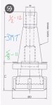
The thread in the top end of my collet chuck is 1/2-12. The largest diameter that can fit down through the spindle is a little over 3/8. A previous owner of the mill had a go at making a drawbar by "welding" a 1" length of 1/2-12 thread onto a piece of 3/8 threaded rod. Both are soft and both are damaged from use. This setup also means that the drawbar can only be removed from the bottom.

It would seem to me to make more sense to be able to remove the drawbar from the top so I don't need to raise and lower the head of the mill if I want to change from a drill chuck to a collet chuck or vice versa mid job.

Here's a pic I found that is pretty close to my collet chuck - I've added thread sizes.

Screenshot_20261104-194112~2.jpg

I tried making a sleeve: 1/2-12 thread outside and M10x1.5 inside. I thought I could screw and loctite this into the top thread in the collet chuck which would let me remove the M10 drawbar through the top. Problem was not enough meat left on the sleeve and it fell apart as I tried to tap the internal M10 thread.

There's also a larger thread at the bottom end inside the collet chuck morse taper - it's 5/8-11. There might be enough meat left if I try the same idea using this....M10x1.5 inside 5/8-11.

Only problem - I have no idea what this thread is used for. Will I be preventing a normal function of the collet chuck if I screw something into this thread ?

Can anyone help ?

As always, all help is appreciated.
 

torch

Well-known member

Equipment
B7100HSD, B2789, B2550, B4672, 48" cultivator, homemade FEL and Cab
Jun 10, 2016
2,897
1,147
113
Muskoka, Ont.
I have a question for you guys more experience with mills and milling than me, that's pretty much everyone.

The thread in the top end of my collet chuck is 1/2-12. The largest diameter that can fit down through the spindle is a little over 3/8. A previous owner of the mill had a go at making a drawbar by "welding" a 1" length of 1/2-12 thread onto a piece of 3/8 threaded rod. Both are soft and both are damaged from use. This setup also means that the drawbar can only be removed from the bottom.

It would seem to me to make more sense to be able to remove the drawbar from the top so I don't need to raise and lower the head of the mill if I want to change from a drill chuck to a collet chuck or vice versa mid job.

Here's a pic I found that is pretty close to my collet chuck - I've added thread sizes.

View attachment 181317
Are you SURE your mill has an MT3 spindle? Because the pictured toolholder sure isn't an MT3 taper. That drawing looks more like a CAT or TC type.