Snowblower help
- Thread starter Snowman7
- Start date
jkrubi12
Well-known member
Equipment
B2601/LA435/QA54"/BH70/B8160box/BB1254/PFL1242/SGC0554/WC-68 Chipper
@GreensvilleJay said.....
"As designed you should ( are supposed to ??) lower blower down, engage PTO,increase RPM to max,use it, reduce RPM to idle, disengage PTO, move to next location, repeat as required.
This sequence should make the coupling last longer, but as designed,sooner or later, it will fail..."
If I'm seeing the K-connect correctly (through the provided pics) the power coupling remains connected until a lever is thrown which is designed to connect/disconnect said coupler. Even if the user engages/disengages the PTO, the 'coupler' remains connected, is this correct?
I've seen provided pictures which show the two halves of the power coupler 'not engaged', with the teeth not fitted into the corresponding spaces. I assume that the 'lever' must be engaged for the teeth to be so close, but that some type of spring, which (in part) provides some movement of the coupling is pressing the teeth together so that engagement will eventually occur with PTO activation. I'm wondering is my assessment is correct, and if the mentioned spring is part of the teeth wear problem. Even with GreensvilleJay's operating advice, if there's a problem with the hardware or design the problem will appear again.
I will continue to follow this discussion as the direction seems to be getting all of us closer to a better understanding of why so many users are experiencing more or less the same malfunction.
GreensvilleJay
Well-known member
Equipment
BX23-S,57 A-C D-14,58 A-C D-14, 57 A-C D-14,tiller,cults,Millcreek 25G spreader,
I'm using the BX2816 blower, BX2810/11 4 point/pto manuals as a reference.
According to what I've read there and the drawings...
When you mount the snowblower on, there is a space between the 'couplings'. You then rotate one until the dogs line up, THEN move the 'engagement lever' ( handle like bar) on the top of the K-connect unit. This slides the front section of PTO shaft and it's coupling, forward to engage/connect to the coupling on the snowblower. This stays 'engaged' or connected 24/7, until you REMOVE the blower in Spring. To actually 'spin the blower', you 'engage' the MM PTO lever,which sends power though the front PTO shafts ,though the couplings and to the blower.
The big problem is that the couplings were not designed for much 'angular' movement, unlike a U-joint or 'ball and socket' couplings. Raising the blower, changes this 'angle', puts tremendous strain on the 'legs' of the couplings and chews them up. Mechanically it's a bit of a nightmare, too many pieces, need for precise alignment and it wears out . They could have cut a pair of gears to do the same function which would never wear out.
No, house full of company all weekend. Blower is on agenda for today.You have confirmed what I already learned by diagnosing the problem with the actual snowblower.
By the looks of the weather it could be weeks before the blower moves any snow. My base is gone and we are in the mud season here. It looks like the end of March. I don’t blow any snow until we have driven over and packed down, and it has to get COLD.No, house full of company all weekend. Blower is on agenda for today.
It turns out hard to get pictures/videos with the geometry of this thing and how close to the ground it is. If I can get a chance soon I'll drive it up on some auto ramps and get the evidence. But from what I can tell, I am not so sure the 'angle of engagement' changes when you lift or lower the hitch. The hitch has two u-joints in it, and the angle of those DO change. The coupling set between the blower and the hitch seems to engage at a perfectly straight angle at all times.
Donystoy
Active member
Lifetime Member
Equipment
LX2610HSDCC, B/H, Loader, plus numerous other attachments. B7200 sold
That is correct. The angle of the blower has no effect on this coupling. The front blower assembly is solidly fastened to the assembly that contains the coupling. These two components are then raised and lowered as a single unit via the hydraulic cylinders. The universal joint on the shaft takes care of the difference in angle. The shaft also telescopes and has to be kept lubricated. If this shaft is not able to freely slide it could possibly contribute to wear to the coupling.It turns out hard to get pictures/videos with the geometry of this thing and how close to the ground it is. If I can get a chance soon I'll drive it up on some auto ramps and get the evidence. But from what I can tell, I am not so sure the 'angle of engagement' changes when you lift or lower the hitch. The hitch has two u-joints in it, and the angle of those DO change. The coupling set between the blower and the hitch seems to engage at a perfectly straight angle at all times.
GreensvilleJay
Well-known member
Equipment
BX23-S,57 A-C D-14,58 A-C D-14, 57 A-C D-14,tiller,cults,Millcreek 25G spreader,
Thanks for telling me HOW the mess is attached... the drawings I could see don't clearly show HOW all the stuff 'fits'. Kinda hard to 'stitch together' the 6 or 7 drawing to see the 'flow of power'.
So, since the blower is rigid to the mount, and the couplings ONLY rotate( spin) , my idea is wrong. A trip to the dealer may have shed some light on this, though if they don't have a blower on a kconnect on a tractor it'd been a wasted trip.
Since the small drive shaft 'pivots', to take care of the up and down, I don't see how the 'couplings' can get chewed. They are engaged once, when blower is mounted to the K-connect. After that they just spin. For them to get damaged,they either are not adjusted properly, something has moved, made of bad steel or badly designed. It might be that the 'engagement lever' isn't moving the coupling/small shaft close enough to the blower's coupling ? It does seems overly complicated and fussy and troublesome.
Sadly, when (if) if ever snows here, I may end up seeing the neighbours BX2380/blower unit....He had TWO techs come out to install it.
Donystoy
Active member
Lifetime Member
Equipment
LX2610HSDCC, B/H, Loader, plus numerous other attachments. B7200 sold
This set up is certainly not the way that I would design it. This coupling design is basically steel on steel. I wonder why they could not have just put in a longer drive shaft and attach it directly with a connection to a spline on the gear reducer. A telescoping driveshaft with universal on either end would work just fine.
On my B7200 I picked up a used front blower assembly from Marsh Brothers and fabbed up the mount and drive assembly to fit the tractor. I designed the drive so that the universal was in perfect alignment with the pivot of the blower when raised . This shaft was also telescoping.
Neither of the universals on the blower in question are aligned with the axis point so it would rely on the telescoping feature of the shaft. That is why I think that maybe if it was partially seized from sliding that it might put pressure on the steel coupling resulting in wear. I will be able to look at mine in a couple of days and see how close the pivot point that the universals are.
Last edited:
I explained what happens when you raise the snowblower and how the two parts spread apart. I showed the pictures, and I stand by my original explanation. You have to remove the 4 cover bolts to see this, which isn't that difficult.
Donystoy
Active member
Lifetime Member
Equipment
LX2610HSDCC, B/H, Loader, plus numerous other attachments. B7200 sold
Dusty, I totally agree with everything that you have stated to diagnose this issue. Just trying to imagine what other forces might be causing the rear half of the coupling to not properly engage the front half and cause wear. I just can't understand the logic in having a metal-on-metal contact and expecting it not to wear. Makes me think of someone trying to use a boston coupling without the rubber insert. If I find that this starts to be a re-occurring issue with my blower and Kubota does nothing to correct it, I will be looking for another means of attachment.I explained what happens when you raise the snowblower and how the two parts spread apart. I showed the pictures, and I stand by my original explanation. You have to remove the 4 cover bolts to see this, which isn't that difficult.
Today I measured the amount of "lift" that the K Connect provides. At the back of the snowblower, it is 12" off the ground, more at the front, but I was looking at the rear because this is where the blower and the K Connect lose contact with each other. I then placed a rubber wheel chock on top of the K connect to limit its upper limit to 6" and I didn't notice as much of a disconnect between the 2 parts. Keep in mind that this is with the blower in a static position, since I wouldn't consider doing this with the safety shield removed. I then tried some wood to make a spacer, but don't have the correct piece to complete my experiment. Today I will be taking a 6" x6"x 10" block of wood to a friend's carpentry shop and will take it down to a 5"x6" and see how that works out to limit the upward movement. I believe that there needs to be something mechanical that prevents the snowblower from moving up too far because when you are pushing snow, your normal hand movements will not be that precise. I will post a picture once I have this done which will help to clarify the issue.
Didn't have a lot of time to do a finished project of my idea, but I did try it to see if my theory will work, and I believe that it will limit the amount of lift that you will get when raising the snow blower. I started with a 6" long piece of 4"x4 and found that it still allowed too much upward movement when placed between the K Connect hitch and the upper bar, so I grabbed a piece of 1"x6" pressure-treated decking and place it on top of the 4 by 4 and then I lifted the snow blower. When I have time I will refine my block to not look so crude, and use some conduit clamps to hold it to the upper bar. This combination of wood allows 6" of upward movement rather than the 12" that it has without the blocks.
The first picture is the blocks sitting on top of the K Connect hitch with the blower sitting flat on the floor, second picture is with the blower raised to the point that the wood stops it from going up any further. The last picture shows the 6" maximum lift that can be obtained using the wooden block.


The first picture is the blocks sitting on top of the K Connect hitch with the blower sitting flat on the floor, second picture is with the blower raised to the point that the wood stops it from going up any further. The last picture shows the 6" maximum lift that can be obtained using the wooden block.
GreensvilleJay
Well-known member
Equipment
BX23-S,57 A-C D-14,58 A-C D-14, 57 A-C D-14,tiller,cults,Millcreek 25G spreader,
I'm trying to 'see' what's happening using the BX2810 install sheet and have a
question...
Does the 'engagement lever' actually 'lock' into a notch to KEEP the 'tractor side of the clutch' engaged to the blower clutch piece ? Looking at the drawings, like Figure #14, it looks like just 'over center' and spring tension keeps the mechanism 'engaged'.
If that's true( springs only, NO retaining notch ) then it's quite possible it may move backwards due to, um,gee... vibrations ?, or PTO on/off cycles.
It'd be a simple test, with safety cover off, raise blower up and try to move the 'engagement handle' backwards, seeing how much force is needed. Maybe bang it a few times to simulate 'plowing into a barrier' ?
I'm kinda wishing I had one on my BX23S but.....all I have is RAIN to deal with......and I don't need to blow $5K+ ? on a 'science project' so 2nd best that I can do is offer 'long distance support'.
It is spring-loaded, but it is a powerful spring, and I doubt that it is moving because of the spring. I believe that it is the two plates that are separating as you raise the blower. The blower on my machine will raise 12", and that is why I installed the block to limit that to only 6 inches. I am going to experiment in a few weeks when I am healed and able to do work in the garage again to try to limit the movement to 3".I'm trying to 'see' what's happening using the BX2810 install sheet and have a
question...
Does the 'engagement lever' actually 'lock' into a notch to KEEP the 'tractor side of the clutch' engaged to the blower clutch piece ? Looking at the drawings, like Figure #14, it looks like just 'over center' and spring tension keeps the mechanism 'engaged'.
If that's true( springs only, NO retaining notch ) then it's quite possible it may move backwards due to, um,gee... vibrations ?, or PTO on/off cycles.
It'd be a simple test, with safety cover off, raise blower up and try to move the 'engagement handle' backwards, seeing how much force is needed. Maybe bang it a few times to simulate 'plowing into a barrier' ?
I'm kinda wishing I had one on my BX23S but.....all I have is RAIN to deal with......and I don't need to blow $5K+ ? on a 'science project' so 2nd best that I can do is offer 'long distance support'.
jkrubi12
Well-known member
Equipment
B2601/LA435/QA54"/BH70/B8160box/BB1254/PFL1242/SGC0554/WC-68 Chipper
Looking at the 'two plates' mentioned by @DustyRusty, it's easy to see how the 'teeth' (engagement lugs?) machined into each of the plates have an angle to them, which appears to be intended to keep the teeth engaged. The two plates could have been designed with flat-faced 90-degree teeth, but Kubota has produced them with an angle on the teeth that seems to be designed to increase the likelihood of maintaining tooth engagementent.
It would seem that the Kubota engineers recognized the possibility of the teeth becoming 'disengaged' while in use, and the terrible effects of the teeth spinning under power, becoming disengaged, and then re-engaging. Ouch!
The pictures I've seen of tooth damage certainly appear to indicate that the damage was sustained during power application when the teeth became disengaged and then re-engaged; or perhaps were somehow engaged while under power. I would really like to hear more from users about the 'solidity' or 'secureness' of tooth connection once the K-Connect power engagement connection 'lever' is thrown; and whether there is a possibility of user-induced problems from improper blower attachment, incomplete/improper connection lever 'throwing' or just general looseness of the K-Connect setup. How secure is that engagement lever once it's moved to 'connect' position?
Update, I finally got to the blower. Winter left and we had a lot going on in the last three weeks.
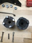
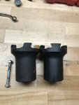
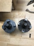
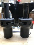
Here are some picks of couplings, new and old. It has not left garage yet but probably will today.
I am nervous to be honest.
Here are some picks of couplings, new and old. It has not left garage yet but probably will today.
I am nervous to be honest.
Attachments
-
 443.4 KB Views: 118
 -
 450.4 KB Views: 118
 -
 402.3 KB Views: 125
 -
 366.4 KB Views: 114
 -
 376.7 KB Views: 123
The Allen set screw on the male coupling keyway was loose. That is the only thing that was off. Do you think that could have been the problem? I do not see how that could be an issue. The bolts keepUpdate, I finally got to the blower. Winter left and we had a lot going on in the last three weeks.
Here are some picks of couplings, new and old. It has not left garage yet but probably will today.
I am nervous to be honest.
both couplings from moving, right? The female coupling( blower ) does not have a keyway set screw. The second to last pic is of both new couplings on and engaged. I think they should be closer when engaged, but everything is put back together and that is what we have.
ve9aa
Well-known member
Equipment
TG1860, BX2380 -backblade, bx2830 snowblower, fel, weight box,pallet forks,etc
That's some serious damage.
DustyRusty (I think) had a separate thread where he thought (I am paraphrasing) the wear and tear on those parts was from running the blower with it raised up off the ground. (someone correct me on that if not so)
I am sure he'll see this thread, or someone else can fill in the details.
I worry about that now! I generally raise my blower only a very little(an inch or two) when backing up, but sometimes do raise it WAY UP (for various reasons I won't go into).
Makes me nervous! (don't want that repair)
Thanks for posting pix !
GreensvilleJay
Well-known member
Equipment
BX23-S,57 A-C D-14,58 A-C D-14, 57 A-C D-14,tiller,cults,Millcreek 25G spreader,
wow, picture are worth MORE than 1000 words !
1st, have to wonder why the faces of the 3 tangs( or 'teeth' of the coupling is picture #1 are shiny. My 'reading' of the instructions is that you line up the couplings, then pull the 'engage' bar forward to engage the coupling sections. This is done once per install,unless you remove the snowblower section.
2nd,there's a LOT of 'slop' between the 'teeth'.Looks like they machined away far too much material when they were made.
3rd. In the 'installed' photo, there's maybe only 1/3rd of the teeth 'face' that actually mate ! That alone will cause a LOT of wear (anyone seen 'chewed up Bendix gears ?? )
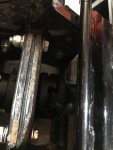
4th. it'd be interesting to see pictures of the 'joinery' when blower is 'fully down' AND 'fully up'. My understanding is they should be the same. The blower side coupling is fixed, The tractor side coupling is also fixed,on front side of the bearing plate, rear has the small shaft with Ujoint.
If the 'joinery' changes between down and up, there is a serious design/build flaw with the system. I consider this 'connection' to be a 'dog clutch'. It's engaged ONCE,then power is applied when needed. A normal 1" Lovejoy coupling would easily do the job.
1st, have to wonder why the faces of the 3 tangs( or 'teeth' of the coupling is picture #1 are shiny. My 'reading' of the instructions is that you line up the couplings, then pull the 'engage' bar forward to engage the coupling sections. This is done once per install,unless you remove the snowblower section.
2nd,there's a LOT of 'slop' between the 'teeth'.Looks like they machined away far too much material when they were made.
3rd. In the 'installed' photo, there's maybe only 1/3rd of the teeth 'face' that actually mate ! That alone will cause a LOT of wear (anyone seen 'chewed up Bendix gears ?? )
4th. it'd be interesting to see pictures of the 'joinery' when blower is 'fully down' AND 'fully up'. My understanding is they should be the same. The blower side coupling is fixed, The tractor side coupling is also fixed,on front side of the bearing plate, rear has the small shaft with Ujoint.
If the 'joinery' changes between down and up, there is a serious design/build flaw with the system. I consider this 'connection' to be a 'dog clutch'. It's engaged ONCE,then power is applied when needed. A normal 1" Lovejoy coupling would easily do the job.