@MartinmMc
Was there any load on the three point hitch when it was lifting on the test (directional valve anti-clockwise)? Was it performing any work or just lifting the arms?
No load on the arms
@MartinmMc
Was there any load on the three point hitch when it was lifting on the test (directional valve anti-clockwise)? Was it performing any work or just lifting the arms?
It does not matyer. The arms came up so the pump is working.No load on the arms

The direction valve rotates, but doesn't have stop, just rotatesI think we need to slow down and confirm a few things.
The directional valve should be fully CLOCKWISE. The OP needs to CHECK AND CONFIRM that. Once confirmed it should never be changed.
I would also l8ke to know why there is a quick coupler on the outlet block
Dan

Yes I've stood on the armsIt does not matyer. The arms came up so the pump is working.
Check and confirm the position of the selector valve on the outlet block. Put your hands on it!! Thats essential information.
Dan
Your three point is working so the pump is working. The loader and remotes are not workingYes I've stood on the arms
Your three point is working so the pump is working. The loader and remotes are not working
That absolutely screams the selector valve on the outlet block is in the wrong position. Focus on it. It should not turn freely - it should have stops .
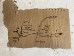
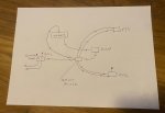
Your new diagram looks a little more understandable but it still has problems. Show me a picture of the connection I circled. I don't see how that is possible.
And please - quit calling the remotes power beyond. They are REMOTES and the lever is the REMOTE CONTROL LEVER
Dan
View attachment 155416
The circled area is the a return flow into the top of the transmission case, I think you were referring to it as the tank.Your three point is working so the pump is working. The loader and remotes are not working
That absolutely screams the selector valve on the outlet block is in the wrong position. Focus on it. It should not turn freely - it should have stops .
Your new diagram looks a little more understandable but it still has problems. Show me a picture of the connection I circled. I don't see how that is possible.
And please - quit calling the remotes power beyond. They are REMOTES and the lever is the REMOTE CONTROL LEVER
Dan
View attachment 155416
The outlet block is the one up by the floor boards. If your remote valve dumps into the top of the transmssion case this may have "worked" but it could never have worked correctlyThe circled area is the a return flow into the top of the transmission case, I think you were referring to it as the tank.
What is the outlet block you refer to? is it the block I arrowed or is it the block on the remote lever?
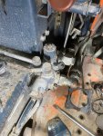
That is not a bolt - it is a valve stem. It is supposed to rotate but there are supposed to be two more roll pins in the surface pointed to by the red arrow. Those two roll pins stick up and are stops for the valve. Clean up the top of the valve and you should find holes for the missing roll pins.Hi Dan
I owe you an apology about schematic for the hydraulics, see amended sketch.
Also another pic of the outlet block , the bolt with the roll pin in just rotates, is it meant to be threaded, what should it do?
It's 10.30 here in the UK, so I'll update you tomorrow.I am 5 hours behind you and will watch this thread for at least another 5. By that time it will be the wee hours of the morning where you are
Dan
