Wiring Diagrams

Chuck Saylor

New member

Equipment
tiller back blade brush hog
Aug 16, 2019
23
0
1
Vancouver Wa USA
Dave it is not like your pictured one which I think has 6 terminals. No cap screw either.. The cap just locks in place with dimples in the cap and base. You read me right, the regulator only has 3 terminals or posts as I called them. The points inside are strange to me also. One arm of the points has a contact, then there is middle arm that has a contact on both sides followed by another arm with only one contact. I assume the center arm moves back and forth depending when the alternator is producing power or not.
Hope I am making myself clear to you.
Thanks Chuck
 

Chuck Saylor

New member

Equipment
tiller back blade brush hog
Aug 16, 2019
23
0
1
Vancouver Wa USA
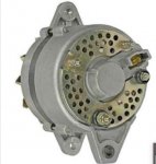
Yes it does from what I can see when I look at the picture. My alternator has a 3 terminal plug in at the top. The top terminal is horizontal and has the letter (E) above it. The bottom 2 terminals are horizontal. The left one has the letter (F) next to it and the right one has the letter (N) next to it. One the far right side of the alternator is a bolt terminal with the letter (B) next to it. I assume your pictured alternator is the same? This is an MCR brand and model # 12068N.
I too am stumped. Thanks Chuck
 

Dave_eng

Well-known member
Lifetime Member

Equipment
M7040, Nuffield 465
Oct 6, 2012
5,124
931
113
Williamstown Ontario Canada
Chuck

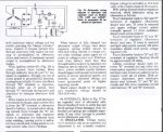
I found a wiring diagram which has a mechanical voltage regulator.

I know you measured the output voltage. Can you do the resistance test I provided on the regulator?

As far as wiring between the alternator and regulator:

E to E and this circuit should be grounded electrically
N to N
F to F

Dave
 

Attachments

Last edited:

Dave_eng

Well-known member
Lifetime Member

Equipment
M7040, Nuffield 465
Oct 6, 2012
5,124
931
113
Williamstown Ontario Canada
Dave since my regulator has no (L) how do I do this resistance test?

Thanks Chuck
Chuck

I have attached more wiring info. It is difficult for me to tell from the diagram except that L is the wire for the no charge light.

One of the two contacts in the regulator is to turn on the no charge light.

Does the new alternator have an amp rating on it? The system was designed for an alternator with an output of only 10 amps and the regulator has no provision to control the amp output. If the new alternator is a greater output, it is concerning. The wiring will not have been sized for more amps. The battery may not be adequately protected.

Dave
 

Attachments

Chuck Saylor

New member

Equipment
tiller back blade brush hog
Aug 16, 2019
23
0
1
Vancouver Wa USA
Ddave I will study this to see what I can get out of the info you gave me. Will let you know how it comes out as I find out my alternator out put compared to the old alternator. Get back to you with more specific info as soon as I learn it.

Thanks Chuck
 

Chuck Saylor

New member

Equipment
tiller back blade brush hog
Aug 16, 2019
23
0
1
Vancouver Wa USA
Hi Dave. More confusion on my part. I am unable to do the resistance tests you sent me the info on.. My regulator only has 3 terminals IG, F and E. Your info shows an L terminal used for testing which I don't have. After again going over the manuals regulator alternator info so so kindly sent me I am confused. The manual says the non-charge indicator lamp system has 3 terminals just like mine. The manual also shows the charge lamp indicator system as having 6 terminals. That is where my confusion comes in. Before my alternator went bad the charge lamp indicator was working on my tractor. Can you make any sense of this?

Thanks Chuck
 

Dave_eng

Well-known member
Lifetime Member

Equipment
M7040, Nuffield 465
Oct 6, 2012
5,124
931
113
Williamstown Ontario Canada
Chuck.

What did you find the output of the new alternator to be?

This is a critical issue before we go further as I am worried about melting wiring and possibly a fire.

Dave
 

Dave_eng

Well-known member
Lifetime Member

Equipment
M7040, Nuffield 465
Oct 6, 2012
5,124
931
113
Williamstown Ontario Canada
Dave

The MCR 12068N is a replacement for a Denso 121000-0980. That is rated for 35 amps.
Thanks for the info on the MCR alt.

It is because the WSM I found says the original alternator was only rated for 10 amps that I am concerned about just connecting it to the tractor's wiring and its regulator.

The eBay seller's product description was possibly misleading when it said the product was for an L175. Perhaps physically but not in other aspects.

Because Chuck is unable to post any photos, it is very difficult to understand exactly what he has.

The description of the voltage regulator (a mechanical one) seems far to simple to deal with an alternator capable of putting out 3.5 times the design current.

Dave
 

Attachments

Jim L.

Active member
Jun 18, 2014
815
87
28
Texas
Dave

Yes, this is a tough one. At least three configurations: the representation in the L175 original wiring diagram, the nebulous "as modified" in reality, and what could be in the near future.

Metric 3 conductor assuming 75 deg C insulation should handle 25 amps. Maybe add fusible link(s) later but for now too confusing (my opinion).

Mechanical voltage regulator should be okay. Main job is to supply just the right amount of current to the alternator field to meet load demand at given voltage. I don't see this little tractor using a lot of electrical power.

Can't tell if this machine has original wiring or has been modified. So color codes now have no meaning for me. Best way to describe is an end to end description.

Obviously the three-terminal regulator does the job. A six-terminal regulator would allow connection of the charging lamp, and original wiring to ignition switch. The original dynamo had terminals N (Neutral), E (Earth, chassis, ground, -12V), F (Field), and B (Battery +12V). The new generator has the same terminals. New connector for F, E, N to be spliced onto existing wiring.

Loss of oil pressure light, as you said, is probably a fuse, but could be bulb.

Need to caution that any work needs to be done with battery disconnected so as not to destroy alternator/regulator.

Question at this point is if a charging lamp is desired, then go to a six-terminal voltage regulator like original. If no charging lamp, and three-terminal regulator, new wiring instructions, not by color, but by end to end.

My preferred way would be to go with a six-terminal replacement regulator to match the original setup and connector. If no charging lamp, then I would add a voltmeter to the panel.

Would be pleased to hear your thoughts.
 

Dave_eng

Well-known member
Lifetime Member

Equipment
M7040, Nuffield 465
Oct 6, 2012
5,124
931
113
Williamstown Ontario Canada
I am always reluctant to spend other owners money but.... when the owners skills to provide info are limited because photos cannot be provided, I am inclined to suggest he purchase a one wire Denso alternator and not worry about anything regarding a charging indicator although a voltage display could be installed.

Buying a new electronic regulator with 6 wires will just make the installation even more complicated if the terminals on the new regulator are not identified which is likely the case.

These products are just marketed to be plug in and go not a wire by wire setup.

Dave
 

Jim L.

Active member
Jun 18, 2014
815
87
28
Texas
Dave

I agree. Very difficult to provide a prescriptive fix without knowing the condition of the alternator harness and the original six-pin harness and connector.
 

Chuck Saylor

New member

Equipment
tiller back blade brush hog
Aug 16, 2019
23
0
1
Vancouver Wa USA
Hi Dave and Jim. I have tried to respond to your latest questions and info but yhe forum must have reached its limit as it doesn't record my responces any longer. Do I need to start a new thread?
 

Jim L.

Active member
Jun 18, 2014
815
87
28
Texas
Chuck,

Please do not start a new thread.

I've noticed some delays lately which are probably internet problems. So go ahead on this thread with your questions.
 

Chuck Saylor

New member

Equipment
tiller back blade brush hog
Aug 16, 2019
23
0
1
Vancouver Wa USA
Hi Dave and Jim. I have tried to post a reply 6 times without it working but will try once more. I disconnected the 10 gauge battery and ground wires from my original L175 NIPPON-DENSO alternator that went bad and connected them to the new MCR alternator.My old nippon-denso alternator also had a plastic 3 terminal plugin with 3 terminals but is in such poor condition I can not make out the letters next to each of the terminals. My new MCR alternator has a 3 terminal plugin which are as follows. 1 is E, 2 is F and 3 is N. My original nippon-denso regulator has the following letters on it's terminals. 1 is E, 2 is F and 3 is IG. Without reference to color of the wires I know E goes to E and F goes to F. Does N go to IG?
Although the L 175 information you gave says only the 6 terminal plugin regulator has a charge warning light I know mine worked before the original alternator went bad. An AMP meter is a good idea and I can do that.

Thanks Chuck
 

Jim L.

Active member
Jun 18, 2014
815
87
28
Texas
Chuck,

I think that it would be better to let one guy tell you how to wire this up, which would be Dave.

Theory, I will be glad to share.

Unless you have an old style amp meter that the needle can move both left and right, then I think that you want a voltmeter. You would want to connect the voltmeter on the switched side of the power.

B is still Battery where the big honking wire is attached, and it is +12V.

E (Earth) is the negative side where the battery is connected to the tractor chassis.

F (Field) is one side of a coil in the alternator that excites the power, and the regulator keeps the right amount of current flowing through the coil to keep the voltage and amps regulated. So F is also the output side of the regulator.

N (neutral) is the center connection of the power producing coils in the alternator.

IG (Ignition) is switched power coming from a key switch. It is the input to the regulator. So you do not want to connect N to IG.