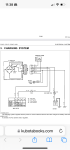
Hi Jay, thanks for the reply. I’m attaching a pic out of the FSM, am I reading it wrong? It shows a circuit off the ignition running over to the regulator. Also, I thought

read somewhere, hard to remember since I’ve read so much, that the regulator needed some type of trigger voltage…I may be mistaken though???
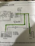
It's not "trigger" voltage in this case, it's feedback voltage. The resistors use it to help control the voltage regulator output.
"Trigger" voltage is when you need power to create a magnet, as I explained in my previous post.
I should have read the schematic before I opened my mouth. Sorry.
If you're having trouble charging, I wouldn't think that would be the issue; only if you were over charging. But, I have no personal experience with these, so take it for what it's worth.
You have gone off in the wrong direction.
Your machine, like many Kubota's has a dynamo to provide the charging current. This is not an alternator!!!
A dynamo is like the light you had as a kid on the front of your bicycle rubbing on the tire sidewall.
It had some permanent magnets that rotated around a coil of wire. The magnetic field generated a voltage as it cut through the coil of wire.
The dynamo is working the same way. It has two wire coming off it, both the same color. It produces an alternating current i.e. AC voltage.
The square electronic box that the two dynamo wires connect to is doing two jobs. It is rectifying the AC output of the dynamo to DC or direct current which is needed to charge the battery. It is also limiting the max voltage going to the battery using a ZENER diode.
The dynamo's rarely fail. The regulator/rectifiers do fail.
Forum member Lugbolt has created a troubleshooting guide for dynamo charging systems which I have attached.
In the early days of Kubota's such as B6000, B7100, the regulator rectifier was very simple and had no warning circuits to tell you the battery is not being charged. Over the years additional features have been added by the dynamo has remained a simple device.
Try following Lugbolt's method. Certainly come back if there are things you do not understand.
Dave
Jesus, are we using points ignition too?!
My understanding is that a dynamo uses a commutator instead of a voltage regulator?
I see in the diagram Kubota calls it a dynamo, and yet it has a voltage regulator. Dunno.
I have no experience with dynamos, only what I've read.
Looks like a brushless alternator to me? Lots of ways to skin a cat I guess.....
It is also limiting the max voltage going to the battery using a ZENER diode.
According to the diagram it's actually using resistors, not a zener diode.
Zener diodes have a different symbol than regular diodes.
Still I don't see HOW the 'regulator' actually works,as they don't show any 'control' feature, just a full wave bridge( 4 power diodes) to convert the AC into DC going to the battery.
The resistors are used to control the voltage, with the feedback voltage from the key on wire (yellow?).