Russell King
Well-known member
Equipment
L185F, Modern Ag Competitor 4’ shredder, Rhino tiller, rear dirt scoop

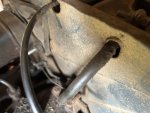
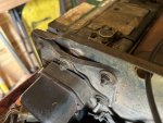
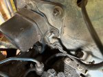
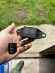
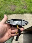
JayYes, sounds like 'classic' overheating of solidstate regulator. I went back to the 3 pictures of how it's mounted and YES the new unit WILL selfdestruct from heat, only a matter of a short time.
I make the assumption that the original regulator,back in the 70s, was an electromechanical type( had relay(s) in it ) and was mounted on that rubber pad to absorb vibration.
The electronic one does not require the 'antivirbration' pad but NEEDS a big 'heatsink'. I'd remove the rubber pad, clean any dirt, grease, grime from the area and bolt the regulator to the 'tin work'. If it won't lay 100% flat to it, cut some thick (1/8-1/4") aluminum sheeting to 3by4, 4by6, whatever size fits in the area, bigger and thicker is better. Use the 'pad' as a template for the 5 holes, but make pad as big as possible.
The back of the regulator is metal and needs to be in contact with metal to get rid of the exess power. which could be 60 watts ( 6volts x 10 amps ), similar to a typical 60W incandescent light bulb. You couldn't put your hand on that !